Microwave
Engineering
Class: Wed = lecture, Fri = review/pre-study(RP),
simulation(SIM)
Grading policy:
5th-week exam
(20%): 4/11
10th-week
exam (20%): 5/9
15th-week
exam (20%): 6/13
Lab (15%)
Homework
(16%)
Class
attendance (10%)
Week-01:
Chapter 1 Introduction
Note supplement: What is microwave engineering?
- Technologies for utilizing high frequency (> 1MHz) electrical signals
- Components > circuits and modules > subsystems > systems >
products > industry > economy > country > world
Lab-01:
Explain the following.
1. The performance of the 5G mobile
communication. List the frequency allocated for 5G mobile communication.
2.
What is the AESA radar used in the F-35 stealth aircraft. List
the performance of the AESA radar of the F-35 aircraft.
Week-02:
Chapter 2 Review of Waves and Transmission Lines
Lab02
- Microstrip line and coaxial cable design
Week-03:
Chapter 3 Antenna Systems
Homework-03
(due 3/29), Solutions
1. Draw the structure of a rectangular
horn antenna.
2. An isotropic antenna radiates 10 mW power.
1)
Find the power density at 100 m away from the radiator.
2)
Find the magnitude of the electric field.
3)
Find the magnitude of the magnetic field.
3. An antenna has reflection coefficient
of -6 dB. Find the VSWR and the reflected power
relative to the incident power.
4. An antenna has gain of 2 dB at 2.4
GHz. Find the effective area (m2) of the antenna.
5. A Bluetooth module transmits a total
of 10 mW at 2.4 GHz with a 2-dB gain antenna.
1)
Find the power density at 10 m away from the transmitting antenna.
2)
The 2-dB gain receiver antenna is at 10 m away from the transmitting antenna.
Find the received power.
Week
04: Chapter 4 Various Components and Their System Parameters
Lab04 -
Microstrip line analysis
Homework-04 (due
4/5), Solutions
1. What is an MMIC?
2. Draw a circuit symbol for a circulator.
3. Draw a schematic for a microstrip
90° (quadrature) hybrid coupler on 50-ohm line base. Specify line lengths and
characteristic impedances. Give ideal values of |S11|, |S21|, |S31|, |S41| in dB.
4. Draw a schematic for a microstrip
Wilkinson power divider. Specify line lengths and characteristic impedances.
Give ideal values of |S11|, |S21|, |S31|, |S23|, |S22| in dB.
5. Draw a parallel R, L, C resonator circuit. Give formulas for
the resonant frequency f0
and the quality factor Q0.
6. Draw a schematic for a through-type microstrip ring resonator on 50-ohm line base. Specify line
lengths and characteristic impedances. Give a qualitative graph in dB for
|S21|.
7. Draw a schematic for a three-section LC band-pass filter.
8. Draw a block diagram of an RF transceiver
comprising of a transmitter, a receiver, a diplexer, and an antenna.
9. What is the microwave detector?
10. What is the microwave isolator?
11. What is the mixer and
the down converter?
12. What is the SPDT switch?
Week-05: Chapter
5 Receiver System Parameters
Lab05a -
Noise figure calculation
Lab05b
- Microstrip quarter-wave transformer
Homework-05: Due
4/12, Solutions
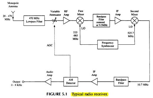
1. Explain the principles of operation of the radio
receiver shown in Fig 5.1
2. What is the sensitivity of a receiver?
3. Calculate the room-temperature (290 K) thermal
noise power at the output of a bandpass filter with center frequency of 900 MHz
and bandwidth of 10 MHz.
4. For the two-stage amplifier shown below,
calculate
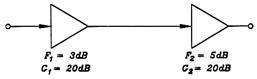
a)
the noise figure
b)
the noise temperature
c)
the output SNR when the input SNR is 12 dB.
5. Convert -85 dBm power into power in watt.
6. A receiver system operates at 200 MHz with the
receiving bandwidth of 1 MHz. The noise floor is
governed by the thermal noise. Input signal level at 1-dB compression point is
-10 dBm.
a)
Find the MDS of the receiver.
b)
Find the dynamic range of the receiver.
Week-06: Test
#1, Lab-05b continued
Week-07: Chapter
6 Transmitter and Oscillator Systems
Lab06
- Microstrip directional coupler
Homework-07: Due
4/25
1. Draw a block diagram of a radio-frequency (RF)
transmitter.
2. List four important performance parameters of an
RF transmitter.
3. What is dBc/Hz in the
spectrum of an oscillator.
4. List four types of noise in an oscillator.
5. What happens if a transmitter has too much phase noise.
6. What is the IM3 products
in a power amplifier. Why is it important?
7. What is the stability of a typical crystal
oscillator?
8. Explain the operating principles of a
phase-locked oscillator in Fig. 6.16.
9. Explain the operating principles of a frequency
synthesizer in Fig. 6.19.
Week-08, Lecture
break for self study
Week-09: Chapter
7 Radar and Sensor Systems
Lab07
- Microstrip T-junction power divider
Homework-08: Due
5/9
A monostatic
radar with following parameters
(Note: A monostatic radar
uses the same antenna for transmission and reception.)
Transmitter frequency: 300 MHz
Transmitter power: 100 kW
Range (the distance from the radar to a target): 10
km
Target radar cross section: 0.1 m2
(stealth aircraft)
Target speed: 700 m/s (Mach 2.06) flying in the line
of sight toward the radar
Antenna gain: 20 dB
1. Find the received power.
2. Find the Doppler frequency.
3. The delay time between the transmitted pulse and
the received pulse.
For a continuous-wave (CW) Doppler radar,
4. Draw a block diagram.
5. Explain the theory of operation.
For a frequency-modulated continuous-wave (FMCW)
radar,
6. Draw graphs of the transmitted signal frequency
and the received signal frequency versus time.
7. Explain the theory of the target velocity
measurement.
9. Explain the theory of the target range
measurement.
Week-10: Chapter
8 Wireless Communication
Exam 2, Chapters 5 to 7 (5/9)
Lab08
- Microstrip quadrature hybrid coupler
Homework-10
1. Find the output SNR at the receiver
Tx:
power = 1 kW, antenna gain = 38 dB
Tx-Rx
distance: 37,000 km
Transmission loss (system loss): -10 dB
Rx: antenna gain = 55 dB, noise figure = 4 dB,
receiver bandwidth = 10 MHz
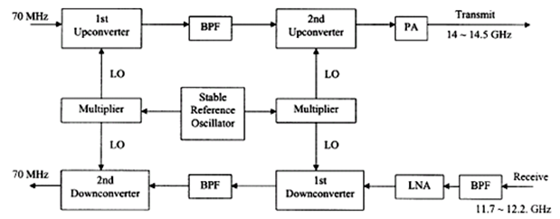
2. Explain the theory of operation of the satellite
communication earth station terminal.
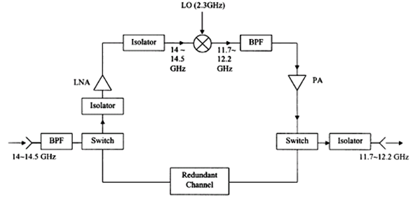
2. Explain the theory of operation of the satellite
communication transponder shown below.
Week-11: Chapter
9 Modulation and Demodulation
Lab09 - Microstrip
ring hybrid coupler
Homework-11
1. What is the modulation index in AM and FM
modulations?
2. Explain the Nyquist sampling theorem.
3. What is the PCM?
4. Explain the principles of the IQ modulator.
5. What is the bandwidth efficiency (= spectrum
efficiency)? What is the theoretical spectrum efficiency of a 64-QAM system?
Week-12:
Chapter 10
Multiple Access
Homework-12
Describe the operating principles of the following
multiple access techniques
1. FDMA
2. TDMA
3. FHSS
4. DSSS
Chapter 11
Wireless Systems
1. Explain the operating principles of GPS
2. Why do you use four GPS satellite signals for
position fix.
3. Explain the operating principles of RFID.
Week-14: Exam 3,
Chapters 8 to 11 (6/7)
Week-15: Study
week break
CST Studio Lab
Lab04 - Microstrip line
Lab05b - Microstrip
quarter-wave transformer
Lab06 - Microstrip
directional coupler
Lab07 - Microstrip
T-junction power divider
Lab08 - Microstrip
quadrature hybrid coupler
Lab09 - Ring hybrid coupler
Lab10 - Waveguide open end radiator
Lab11 - Waveguide magic T junction