Lab05b-Microstrip
quarter-wave transformer
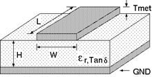
Substrate: ��r = 2.5, Tan�� = 0.002, H = 0.787mm, Tmet = 0.035mm
Use an online microstrip
line calculator: http://www.rfdh.com/rfdb/msline.htm
f
= 2.45 GHz
![]() (quarter-wave transformer design formula)
(quarter-wave transformer design formula)
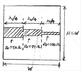
1. Design the following lines.
a) Line 1: Z01
= 50 ��, line length = ��1/4
(a quarter-wave line on a 50-ohm line)
b) Line 2: Z02
= (50*100)1/2 = 71 ��, line length = ��2/4
(a quarter-wave line on a 71-ohm line)
c) Line 3: Z03
= 100 ��, line length = ��3/4
(a quarter-wave line on a 100-ohm line)
2. Make a structure of lines 1, 2, and 3 connected
in sequence.
3. Simulate S11, S12, S21, S22.
4. Analyze the results.
a)
Record |S11| minimum value and corresponding frequency.
(Note:
In theory, |S11| = -�� dB at 2.45GH.)
b)
Record |S22| minimum value and corresponding frequency.
(Note:
In theory, |S22| = -�� dB at 2.45GH.)
c)
Is the reciprocity condition |S12| = |S21| satisfied?
d)
Record the phase of S21 at 2.45GHz.
(Note:
In theory, the phase of S21 will be -270 degrees.)