Chapter 9 Modulation
and Demodulation
8.1 Introduction
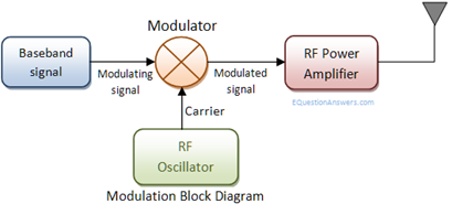
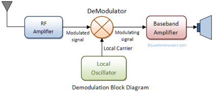
1) Modulation and demodulation
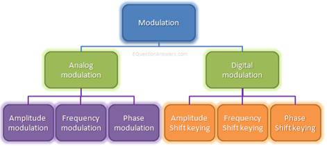
2) Modulation types
Analog: AM, FM
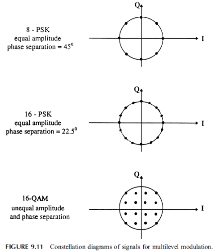
Digital: ASK, FSK, PSK, BPSK, QPSK, 8-PSK, 16-PSK,
MSK, QAM
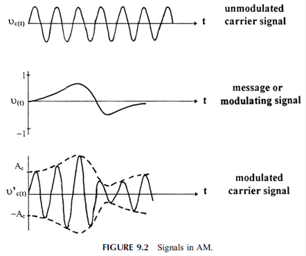
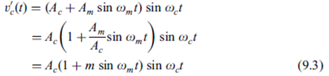
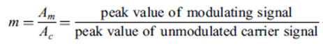
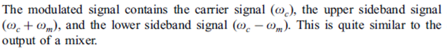
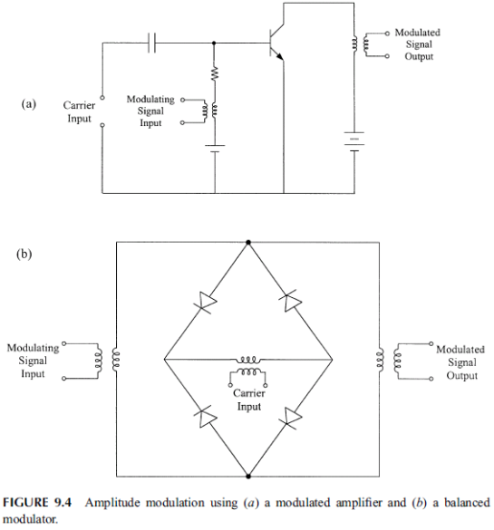
9.2 Amplitude Modulation and Demodulation
![]()
![]()
![]()
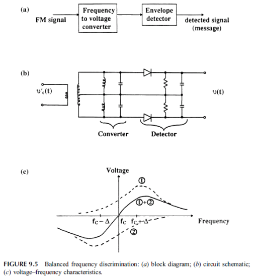
9.3 Frequency Modulation
Modulation: Use a VCO
![]()
Demodulation: Use a discriminator
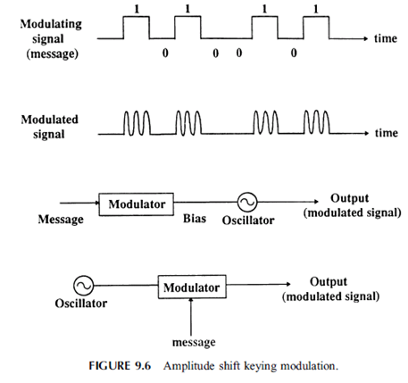
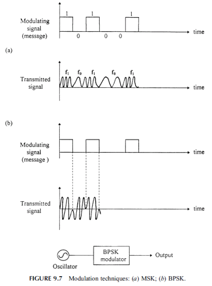
9.4 Digital Shift-Keying Modulation
ASK:
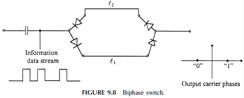
MSK, BPSK:
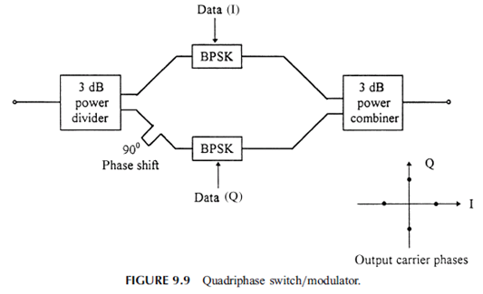
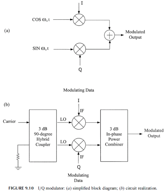
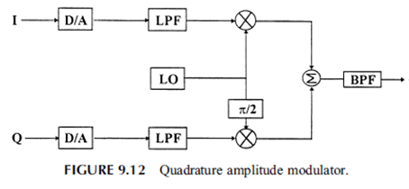
IQ modulator:
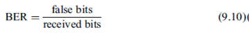
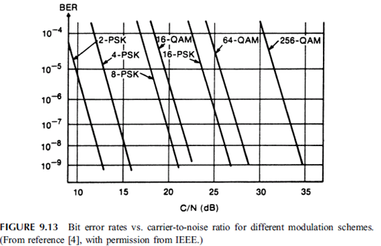
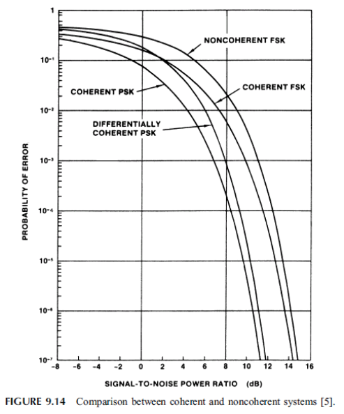
9.5 Bit Error Rate and Bandwidth Efficiency

9.6 Sampling and Pulse Code Modulation
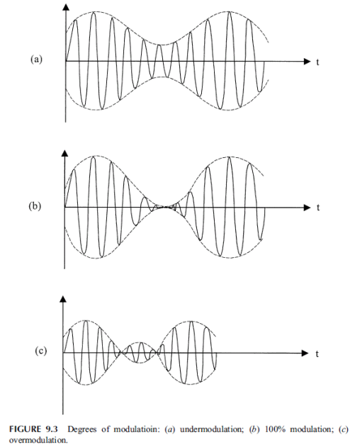
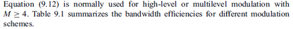
1) Sampling
![]() : Nyquist
sampling theorem
: Nyquist
sampling theorem
Sampling rate = signaling rate: number of samples
per second
PCM bandwidth: fs/2
1Hz band can accommodate 2 samples per second
PCM bandwidth = channel bandwidth
Symbol
rate
Shape
of the pulse to represent the symbols (line code): the bits are represented by Sinc pulses of duration Tb.
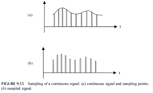
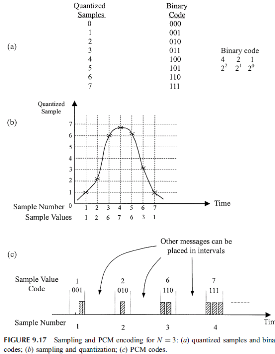
2) Pulse code modulation
Quantizing = Rounding-off to the nearest discrete
value
Encoder = Conversion of a quantized value into a
digital form (analog-to-digital conversion)
![]()
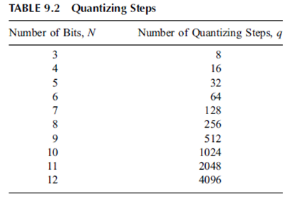
N:
number of pulses to represent a sampled value
Source
coding
Linear
pulse-code modulation (LPCM)
is a specific type of PCM where the quantization levels are linearly uniform. This
is in contrast to PCM encodings where quantization levels vary as a function of
amplitude (as with the A-law algorithm or the μ-law algorithm).
Though PCM is a more general term, it is often used to describe data encoded as
LPCM.
A
PCM stream has two basic properties that determine the stream's fidelity to the
original analog signal: the sampling rate, which is the number of times
per second that samples are taken; and the bit depth, which determines the
number of possible digital values that can be used to represent each sample.
Some
forms of PCM combine signal processing with coding. Older versions of these
systems applied the processing in the analog domain as part of the analog-to-digital process;
newer implementations do so in the digital domain. These simple techniques have
been largely rendered obsolete by modern transform-based audio compression techniques.
Linear
PCM (LPCM) is PCM with linear quantization.
DPCM encodes
the PCM values as differences between the current and the predicted value. An
algorithm predicts the next sample based on the previous samples, and the
encoder stores only the difference between this prediction and the actual
value. If the prediction is reasonable, fewer bits can be used to represent the
same information. For audio, this type of encoding reduces the number of bits
required per sample by about 25% compared to PCM.
Adaptive
DPCM (ADPCM) is a variant of DPCM that varies the size of the quantization
step, to allow further reduction of the required bandwidth for a given signal-to-noise
ratio.
Delta
modulation is a form of DPCM which uses one bit per sample.
Encoding for serial transmission
(= Line coding); related = T-carrier, E-carrier
PCM
can be either return-to-zero (RZ) or non-return-to-zero (NRZ).
For a NRZ system to be synchronized using in-band information,
there must not be long sequences of identical symbols, such as ones or zeroes.
For binary PCM systems, the density of 1-symbols is called ones-density.[30]
Ones-density
is often controlled using precoding techniques such as Run Length Limited encoding,
where the PCM code is expanded into a slightly longer code with a guaranteed
bound on ones-density before modulation into the channel. In other cases,
extra framing bits are added into the stream which
guarantee at least occasional symbol transitions.
Another
technique used to control ones-density is the use of a scrambler polynomial on
the raw data which will tend to turn the raw data stream into a
stream that looks pseudo-random, but where the raw stream can be recovered
exactly by reversing the effect of the polynomial. In this case, long runs of
zeroes or ones are still possible on the output, but are considered unlikely
enough to be within normal engineering tolerance.
In
other cases, the long term DC value of the modulated signal is
important, as building up a DC offset will tend to bias detector circuits out
of their operating range. In this case special measures are taken to keep a
count of the cumulative DC offset, and to modify the codes if necessary to make
the DC offset always tend back to zero.
Many
of these codes are bipolar codes, where the pulses can be positive,
negative or absent. In the typical alternate mark inversion code,
non-zero pulses alternate between being positive and negative. These rules may
be violated to generate special symbols used for framing or other special
purposes.
9.7 Waveform Design for the State-of-Art Digital Mobile
Communication
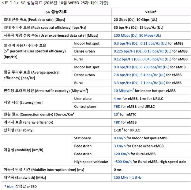
2) 5G Waveforms
- OFDM (orthogonal frequency division multiplexing)
- FBMC (filter bank multi-carrier)
- UFMC (universal filtered multi-carrier modulation)
- GFDM (generalized frequency division multiplexing)
- F-OFDM (filtered OFDM)
- CP-OFDM (cyclic-prefix OFDM)
- CP-DFT-s-OFDM (cyclic-prefix discrete Fourier
transform spread OFDM)
- ZT-DFT-s-OFDM (zero-tail DFT-s-OFDM)
- UW-DFT-s-OFDM (unique word DFT-s-OFDM)