[Tentative topics
[Journals
https://s2journal.bwise.kr/jcr/jcrCategoryRankingPage.do#
https://www.jees.kr/authors/authors.php
; 10 weeks, USD 0
https://www.mdpi.com/journal/electronics
; 6 weeks, CHF 2000
1.
IEEE OJAP: $1950, 4-6 weeks, https://ieeeaps.org/about-ojap https://ieeexplore.ieee.org/xpl/RecentIssue.jsp?punumber=6287639
IEEE Access
IF: 4.1
APC: 1950 USD
2.
https://www.tandfonline.com/loi/uaai20
Applied Artificial Intelligence
IF: 2.8
APC: 1860 USD;
1460 GBP; 1695 EUR
3.
https://ietresearch.onlinelibrary.wiley.com/journal/23977264
HIGH VOLTAGE
IF: 4.4
APC: 1800 EUR; 1600 GBP; 2000 USD
4.
http://www.nature.com/npjflexelectron/
npj Flexible Electronics
IF: 14.6
APC: 2890 EUR; 3690 USD; 2490 GBP
5.
https://pcmp.springeropen.com/
Protection and Control of Modern Power Systems
IF: 11.0
APC: 0
6.
https://link.springer.com/journal/11431
Science China Technological Sciences
이공계 전분야
IF: 4.6
APC: -
[Underway
오대: In-line coax-to-cir transition, submitted to
Electronics Letters(23.8.22), 제1=임동,교신=안병
임동: In-line coax-to-rec transition, sent to 이주(23.8.29), 제1=장경, 교신=서송
배일: Design of a Broadband
Transition from a Coaxial Cable to a Reduced-Height Rectangular Waveguide (배일호, 서송원, 허지원, 이찬수, 안병철)
[Topics
Writing Papers
For Electronics
(2023.3.14 Fred에게 통보)
"Broadband
Impedance Matching of Rectangular Waveguide Open-End Radiators"
Ariunbold Galsan
Yondon, Delger Otgonbat, Jee-Won Huh, Atlanzaya Erdensukh, Chan-Soo Lee* and
Bierng-Chearl Ahn*
[Coax-to-Waveguide
Transition
- Possible topics
Various waguides to
coaxial: bandwidth extenstion, 1.017fc to 2.034fc, WR-75의 경우 8-16GHz
Rectangular
Square
Circular
Double-ridged
Quadruple-ridged
Diagonal
Tall guide: launching, single-mode control,
discontinuities (bends etc.), no paper
https://www.tallguide.com/tal_data.html
https://library.psfc.mit.edu/catalog/reports/2010/10ja/10ja072/10ja072_full.pdf
Ultra-low reflection:
-30dB
Rectangular waveguides
with reduced height
Higher-order mode
generation by transition
Rodriguez https://ieeexplore.ieee.org/stamp/stamp.jsp?tp=&arnumber=7806310
Open double ridge guide
Open quad-ridge guide
[Open
boundary quad-ridged antenna
Rodriguez is the almost
sole author.
[Closed boundary
quad-ridged horn
- Dimensions, 4-10GHz
https://www.jpier.org/issues/volume.html?paper=16121405
[Crossed dipole antenna
- Octave bandwidth
symmetric beam: https://onlinelibrary.wiley.com/doi/10.1002/mmce.22687
Broadband dual-polarized
crossed-dipole antenna with tapered integrated balun for base-station
applications
- Octave bandwidth high
isolation:
A Novel Broadband
Dual-Polarization Antenna Utilizing Strong Mutual Coupling
https://ieeexplore.ieee.org/stamp/stamp.jsp?arnumber=6645430
[Metal Vivaldi antenna
- Dimensions
https://ieeexplore.ieee.org/stamp/stamp.jsp?tp=&arnumber=8600487
[Printed Vivaldi
- Crossed Vivaldi,
high-performance
https://www.litepoint.com/wp-content/uploads/2022/06/UWB-Vivaldi-Dual-Polarized-Antenna-TechSpecs-050522-web.pdf
; 안병철-제안서 그림
- Vivaldi, antipodal, review
- Crossed Vivaldi,
2.6-14.9GHz, dimensions, ###, feng
https://ieeexplore.ieee.org/stamp/stamp.jsp?tp=&arnumber=8563798
- Crossed Vivaldi,
0.56-7.36GHz
https://ieeexplore.ieee.org/stamp/stamp.jsp?tp=&arnumber=7975437
- Taper design only; just
for figure feeling
https://edlib.net/2013/icncre/paper069.pdf
- Dimensions
- Crossed Vivaldi,
dimensions, 2-8GHz
https://ieeexplore.ieee.org/stamp/stamp.jsp?tp=&arnumber=8107496
- Crossed Vivaldi,
dimensions, 3.1-10.6GHz
https://ieeexplore.ieee.org/stamp/stamp.jsp?tp=&arnumber=6036993
- Crossed, high
isolation, dimensions, patterns, 3-18GHz
https://ieeexplore.ieee.org/stamp/stamp.jsp?tp=&arnumber=10023298
- Crossed, back-fed,
0.7-8GHz,
https://ieeexplore.ieee.org/stamp/stamp.jsp?tp=&arnumber=7065249
- Crossed, dimensions,
6-11GHz, thesis
https://scholarworks.umass.edu/cgi/viewcontent.cgi?article=1157&context=theses
- Crossed,
miniaturized, 2.2-13.7GHz, dimensions, ###, li
https://ieeexplore.ieee.org/stamp/stamp.jsp?tp=&arnumber=8992043
[2023-3: Design of A
Widebeam GNSS Antenna
[2023-2:
Design of A Wideband Widebeam Dual-Circularly Polarized Antenna Employing A
Circular Waveguide and A Septum Polarizer
오길선, 모네비
1. Intro
Applications
of the proposed antenna
Review:
waveguide antenna, wideband, widebeam, dual-polarized
This
work: aperture matching, septum polarizer, coaxial probe
II.
Design
Aperture
matching
Septum
polarizer
Coaxial
probe
[2023-1:
Design of A Monopulse Reflector Antenna with
Dual-circularly Polarized Sum Channels and Linearly-polarized Azimuth and
Elevation Difference Channels
[Back logs
Ominidirectional
Circularly-Polarized Antenna Using A Skew Pinwheel Radiator: 오길선
Wideband
semi-dual-polarized monopulse feed: 오길선
Design of A
Full-Band-Matched Rectangular Waveguide Open-End Radiator: 오길선
Wire-Grid
Implementation of A Coaxial Double-Sleeve Balun for Feeding Dipole Antennas: 허지원
Widebeam
Circularly-Polarized GPS Antenna Employing Crossed-Dipoles: 서송원, 모네비
Sporer
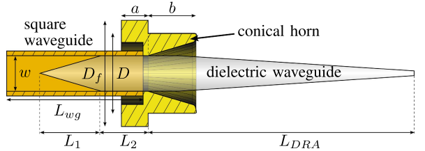
Fig. 2. Waveguide-to-DR
transition. Dimensions: a = 5, b = 11, D = 18, D f = 25, w = 8, Lwg = 35, L1 =
15, L2 = 13, and LDRA = 69 (dimensions in mm). Square waveguide made of copper,
conical horn made of brass, and dielectric rod made of PTFE.
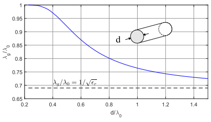
Fig. 3. Guidance
characteristics of the HE11 mode on a cylindrical rod made of PTFE (εr =
2.1). For electrical thick wires (d λ0), c converges the characteristic
velocity of the material c0/ √r thus λg → λ0/ √r.
Regarding the rod
diameter at the feed end dmax, we follow the proposal of Mallach [5] who states
that for optimal radiation characteristics, λg/λ0 along the rod
should be within approximately 0.8 ... 1.0. This range can be mapped to a
physical diameter by examining the guidance characteristics of the HE11 mode
for a cylindrical rod made of Polytetrafluoroethylene (PTFE) as shown in Fig.
3. The curve was calculated by applying the guidance condition for a dielectric
rod formulated by Carson et al. [3] and from [22]. PTFE has been chosen because
it turned out that its permittivity εr = 2.1 allows dmax to be equal to
the inner side length of the waveguide (dmax = w) while obtaining λg =
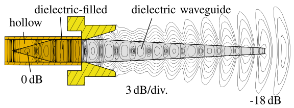
0.84λ0 at the feed end. In this way the rod is mechanically supported and
a stable mounting of the antenna is simplified (see Fig. 2). Further advantages
are good availability and low dielectric losses. A slight exponential taper
guarantees good impedance matching to free-space and reduces the antenna sidelobe
levels [16]. Therefore, our dielectric rod is tapered exponentially from dmax =
w = 8 mm (λg = 0.84λ0) at the feed to dmin = 2.5 mm (λg ≈
λ0) at the end.
![]()
![]()
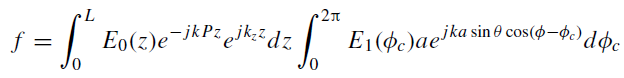
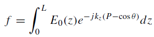
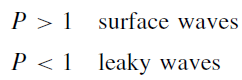
The
pattern peak approaches end fire (θ = 0) as P → 1. By
increasing P beyond 1, the directivity increases and reaches maximum
value for a given P, depending on the length [1]
P = 1 + 0.465/L
(10-8)
Equation
(10-8) is the Hansen and Woodyard criterion for increased directivity of a long
end-fire structure commonly approximated by [2]
P = 1 + 1/(2L)
(10-9)
The
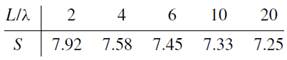
directivity peaks for P given by Eq. (10-8):
directivity
= SL
λ
(10-13)
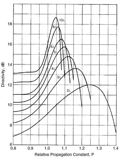
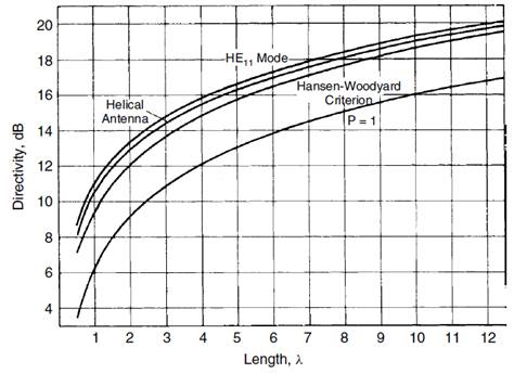
FIGURE
10-2 Directivity of an end-fire traveling-wave antenna.
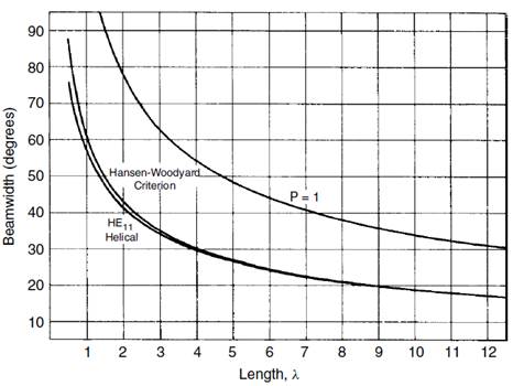
FIGURE
10-3 Beamwidth of a traveling-wave end-fire antenna.
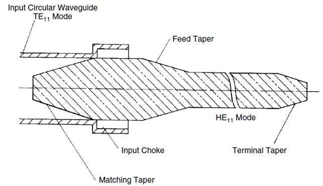
Figure
10-15 shows a common feeding arrangement for the polyrod antenna. The
rod
protrudes from a circular waveguide supporting the TE11 mode, which excites the
hybrid
mode HE11 on the rod. At the waveguide exit we use a rod diameter to give
P from 1.2 to 1.3 so that
the wave will be closely bound to the rod. The feeding guide (Figure 10-15) has
a quarter-wavelength choke to reduce the backfire lobe due
to
direct radiation from the transition [28]. The choke region can also be flared
in a
short
horn [29].
The
second region of the rod tapers either to a uniform diameter section to produce
maximum
gain or to a tapered section to reduce sidelobes. At the end of the antenna we
taper
the rod rapidly in a terminating section to bring the relative propagation
constant of the surface wave near 1, to reduce reflection from the end. We
calculate P along
the
guide and adjust the uniform section diameter or tapered section length to
satisfy
the
total extra phase shift condition for maximum end-fire radiation.
(Example)
The
relative propagation constant for peak gain is independent of the material,
which
we compute from Eq. (10-8): P = 1 + 0.465/5 = 1.093.
By using Scales 10-2
and
10-3, we read the rod diameters: 0.516λ for Teflon and 0.356λ
for Delrin. At the
point
where the rod exits from the feeding waveguide, a suitable relative propagation
constant
is 1.25. We use the scales to find the rod diameters: 0.822λ for
Teflon and
0.456λ
for Delrin. These diameters are proportional to the free-space wavelength,
not
the
wavelength in the rod.