실습-10 적외선 통신(IR Communication)
I. 실습
- 아래 송신회로를 PSpice로 해석

VCC = 5V
MOD = 1kHz, 50%, 5V
R1 = 19.53k for 36kHz
R2 = 1k
R3 = 36.5 for D1 operating with 100mA
@ 1.35V
C1 = 1n
C2 = 47n
D1 = Vishay TSAL6200 →1N4002로 교체
Q3 = 2N2222, 스위치로 동작. 555의 출력 신호가 Q3을 ON/OFF
ㅇ 동작원리
- 555 타이머 36kHz 펄스파형 발생: 3번 단자
- 디지털 신호가 36kHz 펄스파형을 ON/OFF: 4번 단자
- 디지털 신호로 변조된 36kHz 신호는 트랜지스터 스위치 Q3를 구동하여 다이오드(IR 송신 다이오드 TSAL6200으로 교체해도 됨)에 555 타이머의 출력전압과 동일한 파형의 전류가 흐르게 함.
- 다이오드에 100mA의 전류를 흐르게 하고자 하므로 555 타이머 출력 사용 시 전류가 충분하지 않음. 따라서 트랜지스터 스위치 사용
- 변조주파수와 파형
![]()
![]()
- 보고서 작성내용
1) 회로도
2) MOD 신호파형 plot
3) 다이오드 전류파형 plot
II. 이론
참고문헌:
SPIE
Module 1.8, "Fiber optic telecommunication", in Fundamentals of Photonics, SPIE
1. Electromagnetic
Spectrum
Radiowave: 100kHz-300GHz
Infrared: 0.75-1000μm (0.3-405THz). Sun's energy at sea level total 1 kW/m2, 527 W/m2 in IR region
NIR 0.75-3μm
MIR
3-50 μm
FIR
50-300 μm
Infrared-A
0.7-1.4 μm
Infrared-B:
1.4-3.0 μm
Infrared-C
3.0-1000 μm
Visible light: 380-740 nm (405-875THz). Sun's energy at sea level total 1 kW/m2, 445 W/m2 in visible spectrum; red 620-740 nm,
orange 590-620 nm, yellow 570-590 nm, green 495-570 nm, cyan 476-495 nm, blue 450-475
nm, violet 380-450 nm.
Ultraviolet: 10-740 nm, Sun's
energy at sea level total 1 kW/m2, 32 W/m2 in UV
region
Ultraviolet C (UVC):
100-280 nm. Sun's UVC hardly reaches the Earth's
surface due to atmospheric absorption. Used in germicidal lamps.
· Ultraviolet
B (UVB : 280-315 nm. Greatly
absorbed by the atmosphere, and along with UVC is
responsible for the photochemical reaction leading to the
production of the ozone layer.
· Ultraviolet
A (UVA):
315-400 nm. Traditionally held as less damaging to the DNA, and hence used in tanning
and PUVA
therapy for psoriasis.
X-rays: 0.01-10 nm (120 eV - 120 keV). Artificially produced a vacuum tube (X-ray tube).
Cathode emits electrons into vacuum. Anode collects electrons.
A flow of electrons (electrical current, beam) created in the tube.
High voltage power source (30-150 kV) connected across cathode and
anode to accelerate the electrons. The X-ray spectrum depends on
the anode material and the accelerating voltage.
Soft x-
ray 0.12-10 keV:
Hard x-ray
10-120 keV: can penetrate solids, liquids, all uncompressed gases. Used in diagnostic
radiography and crystallography
Gamma rays: 10-100,000 nm
Cosmic rays: Energetic charged subatomic particles, originating in outer space.
Cosmic rays may broadly be divided into two categories: primary and secondary.
The cosmic rays that originate from astrophysical sources are primary cosmic
rays; these primary cosmic rays interact with interstellar matter creating secondary cosmic
rays. The Sun also emits low energy cosmic rays associated with solar flares.
Almost 90% of cosmic rays are protons, about 9% are helium nuclei (alpha
particles) and nearly 1% are electrons.
2. Infrared Spectrum
Usage
NIR(0.74-1μm):
material = SiO2, telecommunication
SWIR(1-3μm): material = InGaAs, PbS, remote sensing
MWIR(3-5μm): material = InSb, PbSe, PtSi, HgCdTe,
high-temperature thermal imaging (indoors, scientific)
LWIR(8-14μm): material = HgCdTe, ambient temperature imaging
(outdoors, industrial)
VLWIR(14-1000μm): material = spectrometry, astronomy
1) Fiber optic communication

Figure: Optical fiber transmission window [IJAREEIE]

Figure: Optical fiber communication distances [InfoCellar]


Figure: Optical fiber modes for communication
[Ad-Net]

Figure: Types of fibers for optical communication
2) Night Vision
- IR illumination or no illumination,
cooled/uncooled detectors, color/gray-scale image


3) Military imaging and homing/tracking
4) Thermal imaging (industrial/medical)
5) Short-range wireless communication
6) IR spectroscopy
FTIR spectrometer (FT = Fourier transform), mostly
based on absorption. Molecules absorb specific frequencies (resonant
frequencies), where the absorbed radiatio matches
frequencies of the bond or group that vibrates.

7) Radio astronomy (for object obscured by stellar
dusts)
3. IR Atmospheric
Transmission

4. IR Sources
1)
Quantum cascade laser: 4-17 μm. Mono mode
or tunable frequency. Narrow linewidth. Power up to 300 mW.
Pulsed 0-2 MHz.
2) Fiber-optic communication
LED: 0.85, 1.31μm
Laser: 1.31, 1.55μm

5. IR Detectors
1) Fiber optic detectors


6. Fiber Optic Communication System Design

ㅇ Dispersion


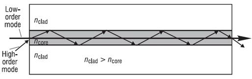
Modal dispersion
Chromatic dispersion
ㅇ Digital encoding
ㅇ Modulation

Direct modulation

External modulation

External modulation with Mach-Zehner
waveguide interferometer
1) Link budget

2) Fiber coupling
3) Wavelength Division Multiplexing (WDM)

EDFA(erbium-doped fiber amplifier)

III. Wireless IR
Communication
1. IR 리모컨 송수신 회로
참고: Peter's
DIY electronic projects: http://jap.hu/electronic/
1) IR 리모컨 동작원리
-
Carrier 주파수: 32-56kHz로 IR 다이오드 변조. IR 다이오드의 적외선이 수신 다이오드에 입사됨.
- 32-56kHz 캐리어 주파수를 1-4kHz OOK 변조(MOD 신호). 1-4kbps 전송속도
- IR 수신기 칩은 carrier 주파수로 변조된 신호의 진폭만 검출하여 출력. 보통 MOD를 반전한 디지털 신호 출력
- IR 리모컨 송수신 회로 + 인코더, 디코더, MCU → IR 리모컨
(참고) IR 다이오드를 32-56kHz로 변조하는 이유: 원 데이터 1-4kbps 디지털 신호로 IR 다이오드를 변조하면 감도가 높지 않음. 리모컨 사이에 간섭이 생김. 캐리어 주파수를 다르게 하여 리모컨 사이에 간섭 방지
2) IR 리코컨 송수신 회로

그림: IR 리모컨 회로
R1 = 1k
R2 = 15-22k (15k resistor
+ 10k potmeter), 32-48kHz
R3 = 15 @ 5VDC, 200mA
peak, 35 @ 9VDC, 50 @ 12VDC
C1 = 1n
C2 = 47n
- MOD(4)에 TTL 디지털 데이터 연결
- 범용 송신기 설계: NE555 사용
- 저전력 송신기 설계: ICM7555 (CMOS로 구현된 555), Quad NAND CD4011를 사용하여 gated oscillator 구현.
- 555: IR LED를 변조하기 위한 펄스 발생 IC
- R1, R2,
C1: 555 IC 출력 주파수 결정
![]()
![]()
- C2: 555 IC의 5(CTRL)
단자 termination
- R3: 다이오드의 전류제한
3) 555 타이머 사용
ㅇ 핀아웃

1: GND
2: TRIG.
Open 시 전압 2Vcc/3이 되고 출력(3번) low, Vcc/3 이하일 때 출력 high (Vcc-1.7V)
3: OUT.
Push-pull type.
4: ![]() . Timing 시작점 리셋. 0.7V 이하가 되면 555의 이 시점부터 timing 다시 시작
. Timing 시작점 리셋. 0.7V 이하가 되면 555의 이 시점부터 timing 다시 시작
5: CTRL.
Control access to internal power divider (2Vcc/3 by
default). Normally not used. 미사용시 10nF를 CTRL과 GND 사이에 연결
6: THR. 2Vcc/3보다 클 경우 3번 OUT low
7: DIS.
Open-collector output. 커패시터를 통해 전압방전 가능
8: VCC. 4.5-16V
ㅇ 동작모드
Astable(free-running) mode: 발진기. pulse train, logic clock, tone, security alarm, PWM,
Monostable mode: One-shot pulse generator
Bistable (Schimitt trigger) mode:
flip-flop.
ㅇ 555를 이용한 펄스파형 생성
7(DIS)번 핀 전압 충전: 충전 시작 시 C 전압 0. Vcc로부터 전원을 받아 R1을 통해 충전. 이 때 R1에는 555 IC의 7번 핀 단자와 (R2 + C)가 병렬로 연결되어 있음.
7(DIS)번 핀 전압 방전: R2 + C를 통해 GND로 방전
6(THR)/2(TRIG) 핀: 커패시터 전압이 충전되어 2Vcc/3에 도달하면 OUT = low. 방전되어 Vcc/3에 도달하면 OUT = high
충전/방전 시정수를 조정하여 발진 주파수를 조정할 수 있다.


4) 적외선 LED
ㅇ Vishay TSAL6200

72mW/sr @ 100mA,
±17º, 940nm, 15ns rise time
1.35V, 100mA


그림: 1) Vishay TSAL6200의 전압-전류 특성, 2) Vishay 1N4001 정류 다이오드 전압-전류 특성
5) 적외선 수신기
ㅇ Vishay TSOP324xx Series
- 0.08-45m with TSAL6200 IR diode
- 2.5-5.5V/ 0.45mA, 30-56kHz (depending on type),
0.08mW/m2-30W/m2 irradiance
- xx: modulation frequency in kHZ
- Used with long burst codes (AGC4);
RC-5, RC-6, Panasonic, NEC, Sharp, r-step, Thomson RCA
- Optimized to suppress almost all spurious pulses
from energy saving lamps like CFLs.

그림: Vishay TSOP3xx 적외선 수신 칩, 1) 형상, 2) Schematic
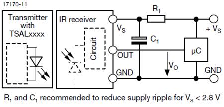
그림: Vishay 적외선 수신 칩 TSOP3xx 응용회로


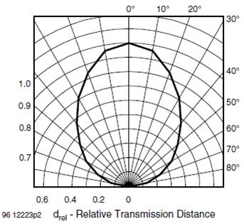
그림: Vishay 적외선 수신 칩 TSOP3xx. 1) 주파수 특성, 2) 주변 적외선 전력에 따른 수신 감도

그림: Vishay 적외선 수신 칩 TSOP3xx. 광입력 신호와 출력 신호

2. IR 음성통신 회로
참고문헌: Loker, "Analog communication
using infrared transmission", PSU lecture note
ㅇ 적외선 통신 실습
1) 송신회로
- 아래 회로를 PSpice로 시뮬레이션 하라.
입력 Vi : AUDIO로 표시된 단자. 100-20kHz 범위의 정현파 신호, 크기 조정 필요
출력 Io : MLED81에 흐르는 전류
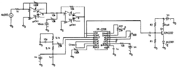
![]() : 주파수 영역 전달계수를 0-30kHz 범위에서 plot하라.
: 주파수 영역 전달계수를 0-30kHz 범위에서 plot하라.
2) 수신회로
- MRD821: 전류원으로 교체, Ii
; 100-20kHz 범위의 정현파 전류신호, 크기 조정 필요
- 스피커: 8Ω 저항으로 교체, Vo![]()
![]() : 주파수 영역 전달계수를 0-30kHz 범위에서 plot하라.
: 주파수 영역 전달계수를 0-30kHz 범위에서 plot하라.