Transmission Lines
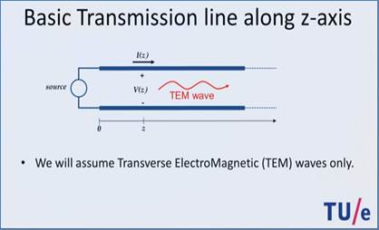
TEM (transverse electromagnetic) wave
- Wave propagation direction: +z
- Ez = 0 and Hz = 0
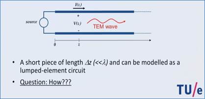
Line length Δz << λ (wavelength)
- The sinusoidal signal does not
change much while the wave travels over Δz
- The transmission line appears to exist
at one point.
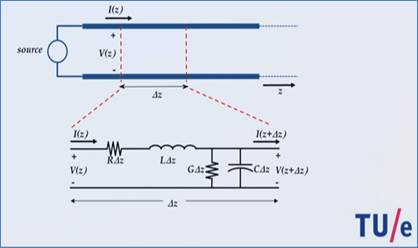
A small section of a transmission line
is represented as an equivalent
circuit shown above.
R, L: Series elements. Resistance and
inductance per unit length (one meter). They are due to metal wires or traces.
G, C: Parallel elements. Conductance and
capacitance per unit length. They are due to material filling the line.
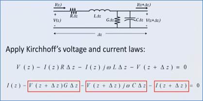
Apply KVL and KCL to obtain the two
equations.
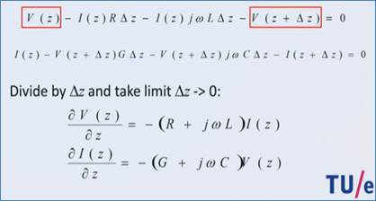
Take a limit as Δz → 0 and divide both sides with Δz to otain a system of partial differential equations for V(z)
and I(z).
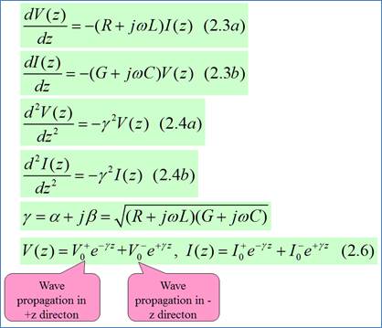
Finding solutions to the
telegrapher's equation.
γ : complex proagation constant
α : attenuation constant
β : phase constant
Waves on a transmission line can
travel in +z and –z directions.
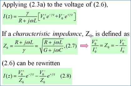
Characteristic impedance: Remember
the definition.
The current wave can be expressed
using V(z) and Z0.
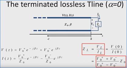
ZL : load
impedance
![]() : either one determined by ZL and Z0.
: either one determined by ZL and Z0.
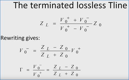
Reflection coefficient: Remember the
definition and its formula.\
Load impedance can be found from the
reflection coefficient:
![]()
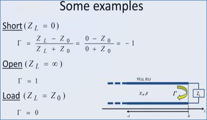
Some special cases:
Short
(단락, 단락회로)
Open
(개방, 개방회로)
Load
(정합, 정합부하)