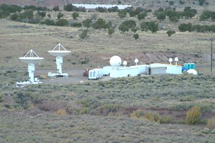
[Kwajalein Telemetry Station]
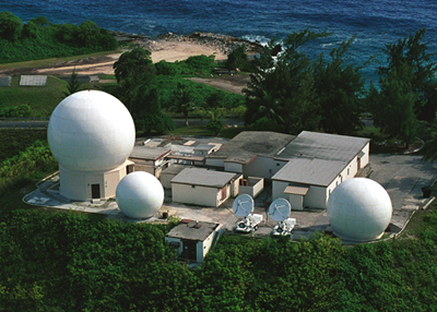
RTS telemetry ground stations
Single-channel concial-scan 1700-2400MHz with 2200-2400 autotrack
capability
S-band omni at Illeginni
4 fixed S-band systems at Gagan
Gagan S-band: 18.5dB @ 2.25GHz, Ts=350K, G/T=-7.5dB, BW=15°, 2.2-2.4GHz
Gagan S-band: 15.0dB @ 2.25GHz, Ts=350K, G/T=-12dB, BW=30°, 2.2-2.4GHz
Roi 3-m L/S-band system: 32.9dB @ 2.25GHz, Ts = 175K, G/T = 11.0dB, 2.8° beamwidth, 1.7-2.4GHz
Roi 5-m L/S-band system: 36.4dB @ 2.25GHz, Ts = 175K, G/T = 16.0dB, BW=1.75°, 1.7-2.4GHz
Roi 7-m L/S-band system: 41.0dB @ 2.25GHz, Ts=350K, G/T=18.5dB, BW=1.3°
Kwajalein 3-m L/S-band system: 34dB @ 2.25GHz, Ts = 175K, G/T=11.0dB, 3dB
beamwidth 3.0°, 1.7-2.4GHz
Kwajalein 5-m L/S-band system: 38.5dB @ 2.25GHz, Ts=175K, G/T=16dB, 1.8° beamwidth, 1.7-2.4GHz
Kwajalein 7-m L/S-band system: 41.0dB @ 2.25GHz, Ts=350K, G/T=18.5dB, 1.3° beamwidth, 1.7-2.4GHz
[Modulation]
PCM/FM
PCM/FM/FM
FM/FM
PM
BPSK
QPSK
FM
Standard IRIG
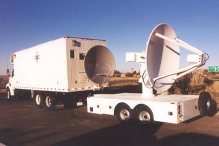
[Mobility]
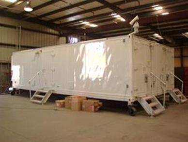
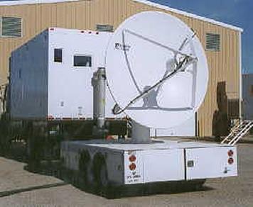
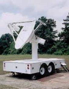
Mobile: TTS(transportale telemetry system)
Stationary
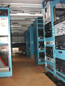
[Equipments and Facilities]
Antenna control (room): dual-axis Kineto Tracking Mount
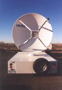
Communications: ground, satellite, ViaSat tracking antenna, SeaTel,
Inmarsat
Data distribution
Data separation
Display
Fiber-optic link
General-purpose tests
Receiving
Recording
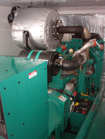
Shelters: electronic equipments, power, SatCom, constructed to ISO 1496-1
Specificic tests
Timing
Tracking: auto-tracking
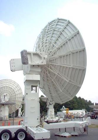
[Types]
Telemetry station: 3-11m reflector antenna
Post impact TM system (PITS): disc-on-rod cone, dual-polarized antenna,
receives wideband TM data signals (2.2-2.4GHz)
[IRIG]
IRIG format serial time codes: IRIG document 200-89
IRIG A: 10kHz carrier, 0.1ms resolution, 1000 pps BCD time of year, A002
time code (pulse width coded = level shift), A132 time code (sinewave AM)
IRIG B: 1kHz carrier, 1ms resolution, 100 pps, B002 time code, B122 time
code
IRIG E: 1kHz carrier, 1ms resolution, 10pps, E002, E122
IRIG G: 1kH carrier, 0.01ms resol., 10kpps, G142
IRIG H: 1kHz, 1ms resol., 1pps, H002, H122
[Shelters]
Inside dimension: 8'W x 8'H x 30'L (39'L)
Paneling: 0.050 AL paneling over AL hatposts
Insulation: Wall and ceiling insulation
Undercarrigage: insulated and finished with 3M undercoating
Lighting: surface mount fluorescent, Vaporite incandescent fixtures
Transportation: flatbed trailer, train, container ship, aircraft
[White Sands Missile Range]
- ViaSat tracking antenna
- Scientific Atlanta 8' dish with E-scan telemetry system
[Glossary]
TRS(telemetry receiving system)
[Technical Information]
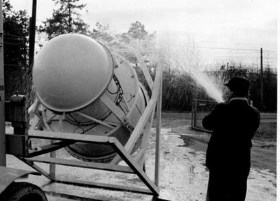
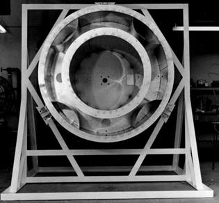
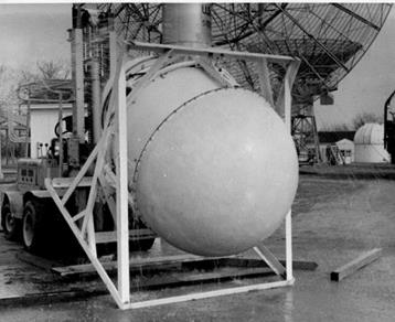
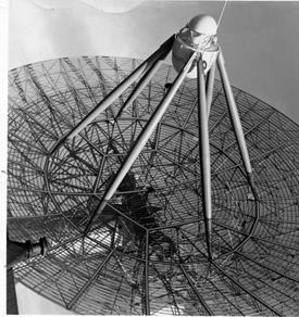
- 6 fiberglass spars tranparent to the antenna frequency: TLM-18 60'
reflector antenna
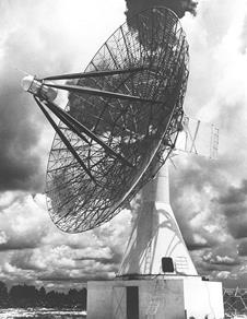
- Single RHCP antenna: TLM-18
- Rotating lens for conical scan: TLM-18, metal disks inserted in a
polyester environment
- Conical scan: 600rmp feed lens rotation → 10Hz
error signal
Received
signal combined with reference signal → I/O signal → mag/phase compared with two reference signals in the demodulator → DC voltages for AZ/EL error (magnitude and polarity) → antenna positioner motor control
- Multicoupler: RF input = 1, RF output = 8
- Sensitivity of tracking signal: well below the sensitivity of data
communication because the bandwidth can be greatly reduced. In TLM-18, 0.2uV at
50ohms = -120dBm
- Sun noise: increases the noise level significantly
- Tracking distance in LOS range:
108MHz: 0.5W 0dBi Tx, 60' Rx
antenna, 71000 mi
- TLM-18 antenna measured performance at 108MHz
G = 29.5dB (sun noise level compared with a standard gain horn)
BW = 5.2°
SLL < -20dB
[Antenna Control]
1. Damage protection features
- Automatic brakes: limit the antenna elevation movement angular range
- Dashpot: velocity limiter, operates if angular speed exceeds 1°/s
2. Antenna wobbling
- AM modulation of incoming signal 4-20Hz: resultant distortion of 10Hz
antenna control signal → antenna is trying to hunt for
target rather than smooth tracking
3. Effect of multipath
- Large scattering objects: launch pad, buildings
- At low angles: below 10° elevation
- Manual operator intervention: video cam's boresight aligned with that of
the antenna, operator manually steers the antenna to the target direction
- Refraction, ducting, reflection, etc. have an effect of
amplitude-modulating the carrier in a random fashion
[Feed Design]
1. TML-18: 216-245MHz, RHCP, 60' reflector, 29.5dB gain, 5.2° BW, SLL < -20dB, circular WG feed with rotating lens concial scan
\