ICT083 Antenna Design
Small Antennas
I. Theory
1. Small Antenna Theory
Antenna
Volume:
- Antenan sphere: A sphere of radius a
entirely encloses the antenna.
- Antenna cylinder: A cylinder of radius a and heigth b encloses
the antenna.
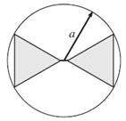
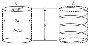
Figure: Antenna sphere and antenna cylinder [Fujimoto (2013)].
Fujimoto (2013), Modern Small
Antennas
Fundamental Limitations of Antennas [Hansen (1981)]
Small
Antenna:
- Size boundary is not clearly defined.
- One that is operated below its natural resonance frequency.
- Dipole resonance: Half-wave dipole, a
= 0.5 λ, ka = π
- Antenna smaller than 0.1 wavelength: a = 0.1 λ, ka = 0.2π = 0.63
- Has fundamental physical limits in gain and bandwith.
- Analyzed via spheical wave mode theory.
Feartures
of Small Antennas
- Electrically small: ka < 1
- Low gain and narrow bandwidth
- Most antennas are a small antenna below 1 MHz.
- Small antennas are inevitable for small platforms:
SoPs, ICs, implantable devices
Radian
Sphere:
- Sphere with radius ![]()
- Antenna length or size in radian wavelength: Multiply by k or divide by λ/(2π)
- Boundary between the reactive near field and the radiationg near field.
1.1 Antenna Efficiency
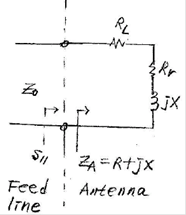
Figure: Circuit representation of a small antenna
![]()
![]()
e : Antenna system efficiency including
the matching network efficiency
Rr : Radiation resistance
RL : Loss resistance
Rc : Conductor loss resistance
Rd : Dielectric loss
resistance
Rm : Matching network
resistance
![]() : Input reflecton coefficient
: Input reflecton coefficient
1.2 Antenna Gain
![]()
D = 1.5 = 1.8 dBi : For all small
antennas
G : Gain
e : Anenna sytem efficiency
D : Directivity
 [Compston (2008)]
![]()
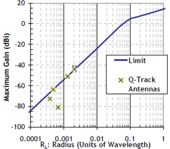
Figure: Maximum theoretical gain of small antennas [Shantz (2005)]
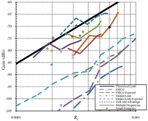
Figure: Small antenna gain [Compston (2008)]
1.3 Bandwidth
Chu limit: Fundamental limit (minimum Q)
of small antennas. Chu (1948), Wheeler (1960), Harrington (1960)
Quality
factor Q:

![]() : R + jX, Series circuit representation of the
antenna
: R + jX, Series circuit representation of the
antenna
![]() : G + jB, Parallel circuit representation of
the antenna
: G + jB, Parallel circuit representation of
the antenna
![]() : Linear polarized antenna
: Linear polarized antenna
Fractional bandwith:

|S11| < –10 dB at ![]()
f0 : Center frequency
B = 10% → Q
= 5
Percent bandwidth:
![]()
Absolute bandwith:
![]()
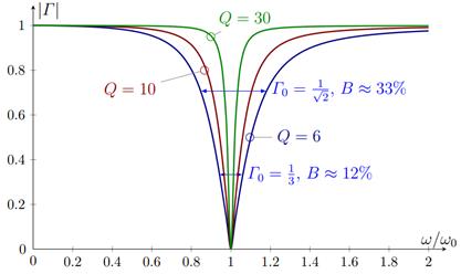
Figure: Reflecton coefficient of an RLC
series resonant circuit with various Q
values [Ehrenborg (2019)]
1.4
Gain-bandwidth product GB:
![]()
1.4 Small Dipole Antennas
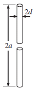
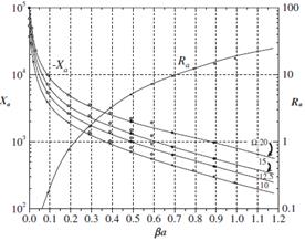
Figure: Small dipole antenna
b: Wire radius, much larger than skin depth
L: Dipole length
![]() : Skin depth
: Skin depth
![]() : Radiation resistance
: Radiation resistance
![]() : Conductor loss
: Conductor loss
![]() : Surface impedance
: Surface impedance
![]() : Reactance
: Reactance
![]()
![]() : Directivity
: Directivity
1.5 Small Loop Antennas
a: Loop radius
b: Wire radius, much larger than skin depth
![]() : Skin depth
: Skin depth
![]() : Radiation resistance
: Radiation resistance
A: Loop area (πa2 for cirular loop, a2 for square loop)
![]() : Conductor loss
: Conductor loss
![]() : Surface resistance
: Surface resistance
Rp
/ R0 : Correction factor due to wire proximity effect.
Neglect if c/b > 3
![]() : Directivity
: Directivity
![]() : Inductance,
circular loop
: Inductance,
circular loop
![]() : Inductance,
square loop antenna with side a and
wire radius b
: Inductance,
square loop antenna with side a and
wire radius b
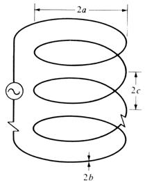
Figure:
Geometry of a multiturn helical loop antenna [Balanis]
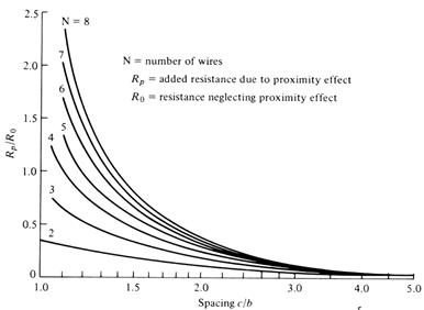
Figure:
Proximity effect correction factor of multiturn loop antennas [Smith]
1.6 Small antenna impedance modeling
- Small dipole

- Small loop

Bibliography
Balanis(2012), Small antennas ans Wheeler's radian sphere
Davis(2010), Fundamental limits on antenna size: a new limit
Shahpari(2018), Fundamental limitations for antenna radiation efficiency
Wheeler(1959), The radiansphere around a small antenna
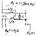
2. Small Antenna Impedance Matching
2.1 Small antenna input impeance
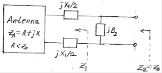
Figure:
Small antenna impedance matching
![]()
R : antenna input restance, R << Z0
X : antenna input reactance, X >> Z0
![]()
![]()
![]() : Antenna feed line characteristic impedance
: Antenna feed line characteristic impedance
- Matching elements
1st element:
Series connection
2nd
element: Parallel connection
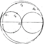
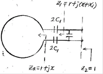
2.2 Impedance matching equations
![]() : Antenna input
impedance divided by 50 ohms.
: Antenna input
impedance divided by 50 ohms.
![]() : Characteristic admittance
: Characteristic admittance
Two solutions:
1st solution:
[Antenna] + [Series L1a or C1a] +
[Parallel C2a]
2nd
solution: [Antenna] + [Series L1b or C1b] +
[Parallel L2b]
The first matching element: Series connection
![]()
b: Negative or positive
![]()
![]()


The second matching element: Parallel connection
![]()
![]()
![]()
Computer program: exe code, source code
2.3 Small dipole and small loop antenna matching
- Small dipole anenna
- Small loop antenna
3. Active Matching of Small Antennas
4. Small Antenna Examples
4.1 Ferrite Loopstick Antenna
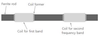
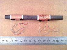
Figure: A ferrite loop stick antenna with
inductance of 0.37 mHz at MW (550 - 1550 kHz) and 4.1 mm at LW (150 - 280 kHz).
The anenna is 120 mm long with 9.5-mm diameter. The anenna is 6×10⁻⁵
wavelength at 150 kHz [www.ebay.ie]
Ferrite loopstick antenna design references:
Koshima (2016), CIA (1957)
4.2 Long
Wave Receiving Loop Antenna
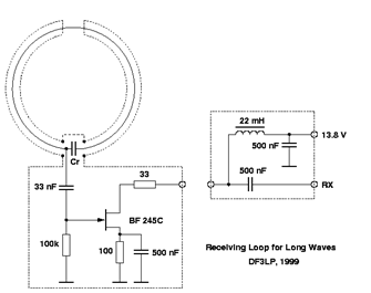
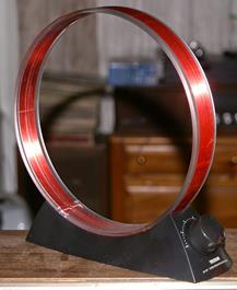
Figure: Left = A 2.2-m diameter (0.00091
wavelength at 137 kHz) loop antenna [DF3LP, 1988 in QSL]
Right
= Tessun AN-100 AM broadcast receiving loop antenna of 224-mm diameter
constructed with 28 turns of 21 gauage varnished magnet wire. It is tunable from
515 kHz to 1850 kHz. The antenna is 0.00038 wavelength at 515 kHz [Antique
Radios].
4.3
Whip Antennas

Figure: A 136-174 MHz whip antenna on Motorola
CP200D digital 16-channel walkie-talkie [Location Sound Corp]. The antenna size
is 128 mm (0.058 wavelength at 136 MHz) including the device chassis.
4.4 식당 호출벨 안테나
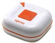
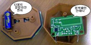
Figure: 좌 = 식당용 무선호출벨, 447.8625 MHz (FM) 50×50×18 mm [엔티티웍스]. 우 = 무선호출벨용 루프 안테나 30×15 mm (0.045 파장) [blog.daum.net/dryer/12293237]
4.5 Ceramic Chip Antenna
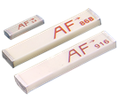
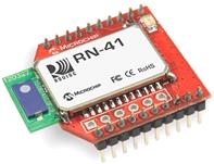
Figure: Left = Ceramic chip antennas for 2.4
GHz (6.5×2.2×1.0 mm), 868 MHz (16×3×1.7 mm), and 916
MHz (16×3×1.7 mm) [Linx Technology]. For the 868-MHz antenna, the size
is 0.046 wavelength. Right = A chip antenna used in a Bluetooth module [NKC
Electonics]
Linx
chip antenna datasheet (2.4 GHz, 868 MHz, 916 MHz models)
4.6 Headphone Antenna
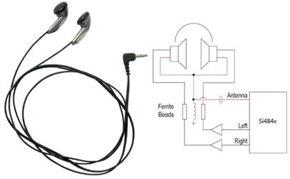
Figure: The headphone wire can be used as
antenna for AM/FM broadcast receivers. An LC-matching
circuit is used. Static charges can easily accumulate on the headphone wire and
the ESD diode (CM1213) is connected before the LC-matching circuit
[Silicon Labs AN602].
Silicon Labs AN602,
"Si4822/26/27/40/44 antenna, shematic, layout and design guideline";
Antenna interfacing for the AM/FM/SW receiver chip