Antenna
Design, Parabolic Reflector
I.
Theory
1.
Optics-based Antennas
- Reflector antennas
- Lens antennas
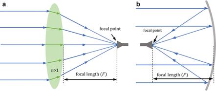
Figure: Optical antennas. Left = lens antenna, right = parabolic
reflector antenna. From C. A. Fernandes et al. in Handbook of Antenna Technologies, Z. N.
Chen et al. Ed. Springer, 2016
- Various types of reflector antennas
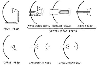
Figure: Reflector
antennas in various forms. After P. Hazdra.
2.
Parabolic Reflector Antenna
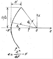
- Theory of operation: conversion of a spherical wave
into a planewave
- Ray path length independent of the ray angle
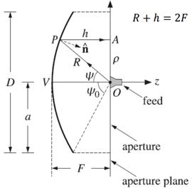
Figure: Geometry of
a parabolic reflector. After P. Hazdra
- Various types of the
reflector antenna
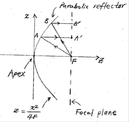
- Origin at the reflector apex
- F-A-A'
path length = F-B-B' path length
![]()
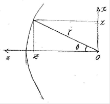
- Origin at the focal point
![]()
![]()
![]()
- Space taper
![]()
- Feed-oriented geometrical equations
![]()
![]()
![]()
3.
Parabolic Reflector Antenna Design Procedures
- Maximum efficiecny
condition
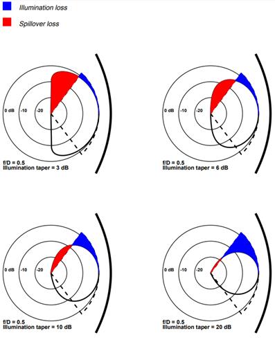
Figure: Feed
illumination loss and spillover loss. After P. Wade
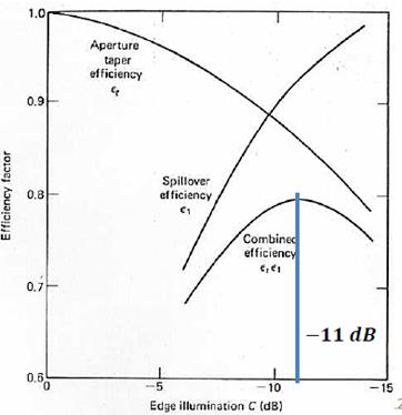
Figure: Optimum
edge taper in the reflector illumination. From P. Hazdra
- Feed taper due to spherical wave spreading
![]()
![]()
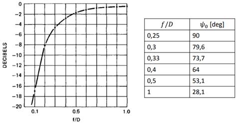
Figure: Spherical
wave spreading loss
- Gain speficied
![]()
- Calculate the reflector diameter assuming 50%
efficiency (when realized).
- Design a feed and find its 10-dB half-beamwidth ![]() .
.
![]()
- Design a parabolic reflector.
![]()
z: axial distance
from the apex
x: radial distance
from the apex
- Simulate the reflector illuminated by the feed.
Full-wave
simulation
Full-wave
symmetrical simmulation: 1/2, 1/4 of the structure
applying the field symmetry
Simulation
using the far field of the feed
- Analyze the reflector performance.
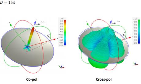
Figure: 3D gain
patterns of a 15-wavelength parabolic reflector. After P. Hazdra
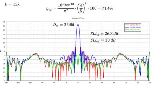
Figure: Cartesian
gain patterns of a 15-wavelength refelctor antenna. After P. Hazdra
4.
Feed Design
- Sidelobe level of a
circular aperture
Uniform circular aperture:
![]() : direcitivity
: direcitivity
a : aperture radius
![]()
SLL
= -17.6 dB : sidelobe level
Uniform rectangular apertuer:
![]()
![]()
SLL
= -13.3 dB
- Tapered aperture
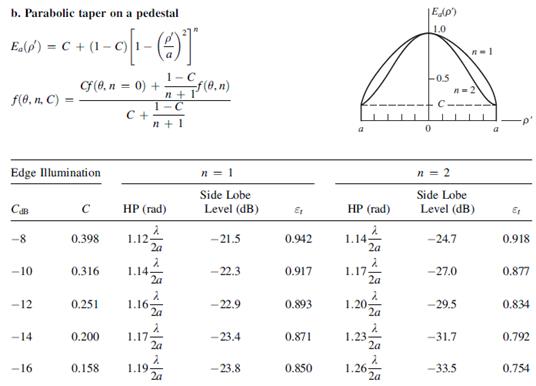
Figure: Performance
of tapered circular apertuers. After W. L. Stutzman.
- Feed types
Horns
for the Cassegrain reflector
Circular
waveguides for the prime-focus parabolic reflector
- Feed performance
10-dB
beamwidth
E- and H-plane pattern symmetry
Cross
polarization level
Phase
center
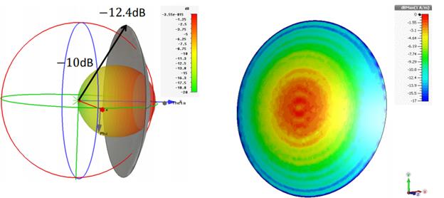
- Feed gain pattern in 3D
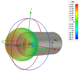
Figure: 3D gain
pattern of a circular waveguide feed. From P. Hazdra
- Feed gain pattern in Cartesian
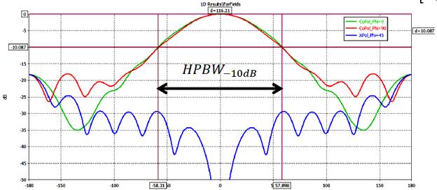
Figure: Cartesian gain pattern of a circular waveguide feed. From
P. Hazdra
- Feed phase pattern

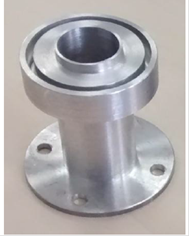
Figure: Phase
pattern of a circular waveguide feed. From O. Garcia-Perez.
- Cicular waveguide feed
Good
E- and H-plane pattern symmetry when the waveguide diameter is 0.65
wavelength.
Backlobe
supperssion: Use a quarter-wave choke around the aperture
E-plane slits (two of them): To improve
the pattern symmetry
5. Reflector Antenna
Analysis
5.1
Radiation pattern calculation
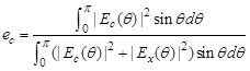
1) 1D aperture integration
- Axi-symmetric case:
![]()
![]() : reflector's pattern angle
: reflector's pattern angle
![]() : feed's pattern angle
: feed's pattern angle
![]()
![]()
![]()
![]()
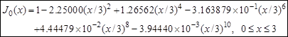
- Calculation of Bessel function J0(x):
Single-precision
Fortran
Modification
of Abramowitz & Stegun for
0.001 accuracy

2) 2D aperture integration
3) Feed blockage modeling
4) High-frequency methods
- PO
- Ray methods: GTD, PTD, UTD
- Effects of the aperture blockage
Efficiency
decrease due physical blockage: simple formula available
Sidelobe increase: simple formula available
Feed
diffraction/scattering efficiency loss: graph available
- Main reflector rim diffraction
Backlobe increase at 180°: main reflector rim
diffractions add in phase.
Reduction
of rim diffraction:
Rim
edge: rolled, castellated, serrated
5.2
Efficiency calculation
- Maximum directivity
![]() : maximum possible directivity
: maximum possible directivity
Ap
: antenna aperture's physical area
![]()
- Realized directivity
![]()
![]()
![]() : antenna
aperture efficiency
: antenna
aperture efficiency
![]() : feed blockage
efficiency
: feed blockage
efficiency
![]() : feed
diffraction efficiency
: feed
diffraction efficiency
![]() : feed amplitude taper
efficiency
: feed amplitude taper
efficiency
![]() : feed phase
efficiency
: feed phase
efficiency
![]() : feed spill-over
efficiency
: feed spill-over
efficiency
![]() : feed cross-polarization efficiency
: feed cross-polarization efficiency
![]() : implementation efficiecy. Main
reflector surface error, feed dielectric loss, feede
reflection loss
: implementation efficiecy. Main
reflector surface error, feed dielectric loss, feede
reflection loss
- Feed mismatch or reflection efficiency
![]()
- Feed lockage efficiency:
![]()
- Amplitude taper efficiency:
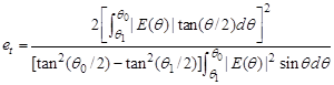
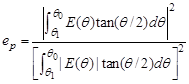
- Phase error efficiency:
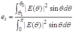
- Spill-over
efficiency:
- Cross-polarization efficiency:
- Efficiency
in dB
|
Efficiency |
Decibel (dB) |
|
1.0 |
0 |
|
0.9 |
– 0.46 |
|
0.8 |
– 0.97 |
|
0.7 |
– 1.55 |
|
0.6 |
– 2.22 |
|
0.5 |
– 3.01 |
|
0.4 |
– 3.98 |
|
0.3 |
– 5.23 |
5.3
Accurate analysis of reflector antennas
- High-frequency methods-based commercial software
package
Grasp
ICARA
- Full-wave analysis package
CST
Studio
HFSS
FEKO
- Literature
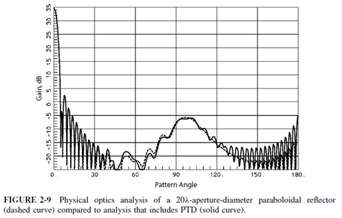
1) Milligan: p. 65
20-lambda parabolic reflector with -12dB taper illumination
Sidelobe around 100°: due to feed spillover
PO: accurate up to 120 degrees off axis
PTD: accurate up to 180 degrees off axis
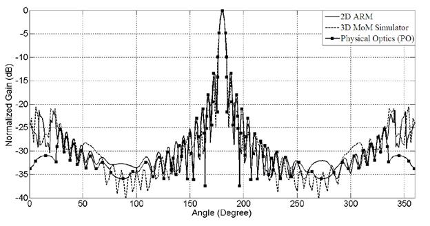
2) Yurduseven(11-ieee):
ARM (analytical regularization method): 2-D problem,
E-polarized wave diffraction by arbitrary shaped, smooth and PEC cylindrical
obstacles
3) Oguzer(95-ieee)
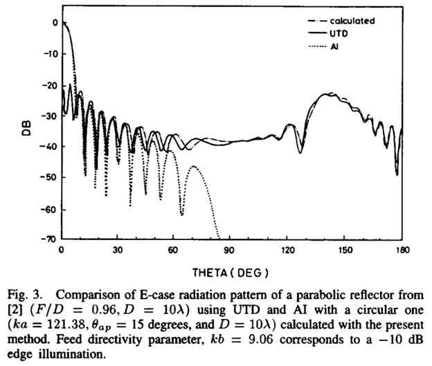
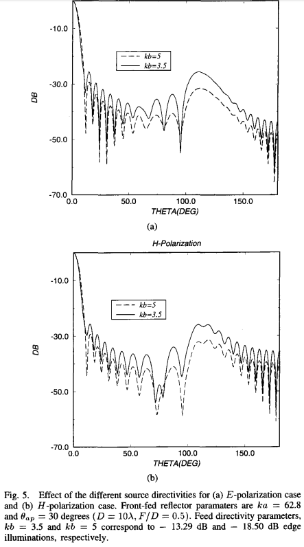
a: main reflector
radius
b: feed radius
5.4 Front-to-back ratio estimation
Milligan, p. 399
![]()
G :
antenna gain
T :
feed taper ( > 0)
Gf : feed gain
![]()
6.
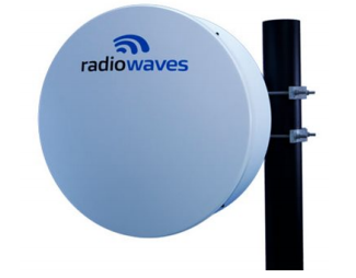
Reflector Antenna Product Specs.
ETSI Class 2/3
Dia 0.6m
Pol single
Freq: 7.75-8.5GHz
Gain: 30.4-31.6dB
Beamwidth: 4.5°/4.5°
X-pol: 30dB
F/B: 54dB
VSWR: -16dB (1.37:1)
7.
Reflector Antenna Examples
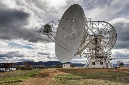
Figure: A 26-m prime-focus parabolic reflector antnena and a 12-m AuScope VLBI antenna at the Mount Pleasant Radio Observatory (Australia). From Wikipedia
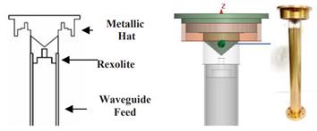
Figure:
High-performance backfire feed. From Garcia-Perez.

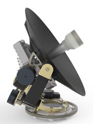
Figure: Left = General Dynamics uPak C060QDA 60-cm reflector antenna for SATCOM on the move (SOTM) operating at Ka, Ku, and X bands. Right = Skytech 30-cm ADE reflector for SOTM (Rx 10.7-12.75 GHz, Tx 13.75-14.5 GHz)

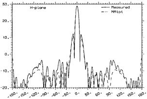
Figure: Gain patterns of a 10.3-λ backfire fed parabolic reflector antenna. From Kildal, IEEE T-AP, 45(7), 1997
References
[1]
T. A. Milligan, Modern Antenna Design,
2nd Edition, IEEE-Wiley, 2005.
[2] W. L. Stutzman and G. A. Theiele,
Antenna Theory and Design, 3rd Edition, Wiley,
2013