L10 - Microwave Filter
I. 이론
1. 필터 기초
ㅇ 필터의 종류: 원하는 주파수 성분만 통과 또는 차단
ㅇ 용도: 신호간섭 피해 방지, 간섭신호 발생 방지
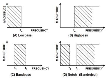
ㅇ 종류:
저역통과필터(LPF)
고역통과필터(HPF)
대역통과필터(BPF)
대역저지필터(BSF)
ㅇ 특수 필터
다중 대역통과필터
멀티플렉서
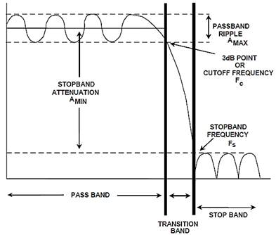
ㅇ 필터규격
- 주파수: 차단주파수 (LPF, HPF), 중심주파수 및 대역폭 (BPF, BSF)
- 통과대역 감쇠 (dB)
- 통과대역 리플 (dB): Chebyshev filter의 경우
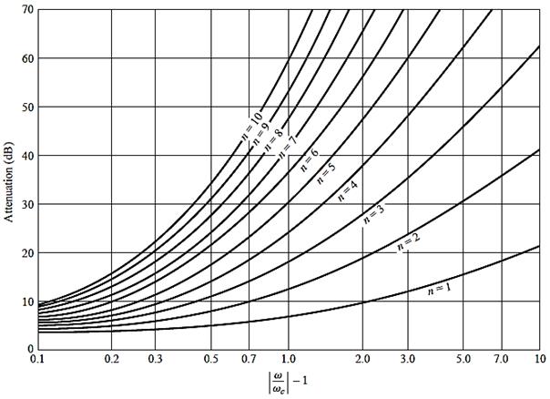
- 차단대역 감쇠 (dB): 필터의 차수 결정. 예: LPF의 경우 1.5fc에서 40dB
- 크기
- 중량
- 온도범위
ㅇ 필터형식 (종류)
Butterworth
filter
Chebyshev
filter
Elliptic
(Cauer) filter
Bessel
filter: maximally flat linear phase response, preserves the signal shape
Gaussian
filter
Optimum
"L" (Legendre) filter
Linkwitz-Riley
filter
Image
impedanc filter
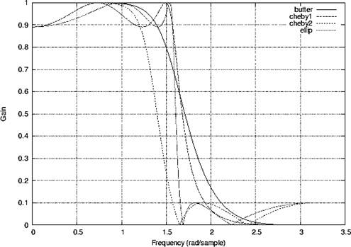
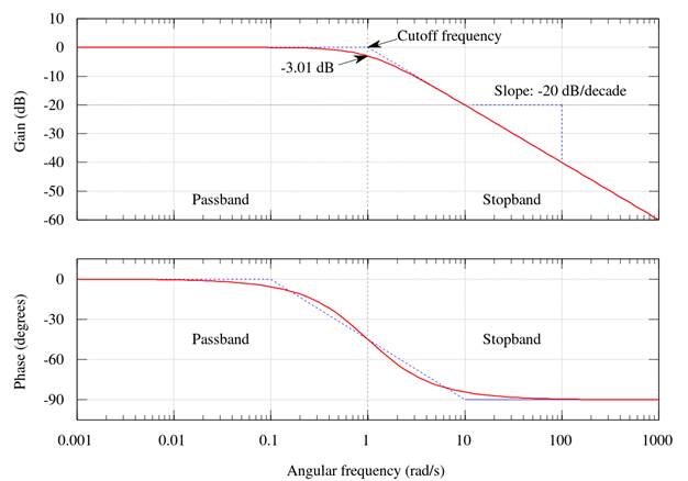
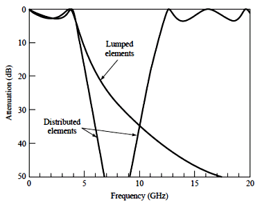
ㅇ 필터의 통과대역 주파수 특성
- 전달계수 (출력전압을 입력전압으로 나눈 값) 특성
주파수에 따른 크기 특성: 감쇠 (attenuation0
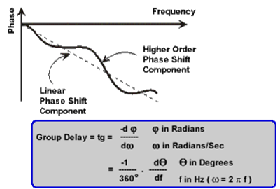
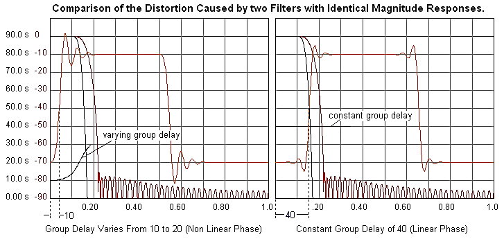
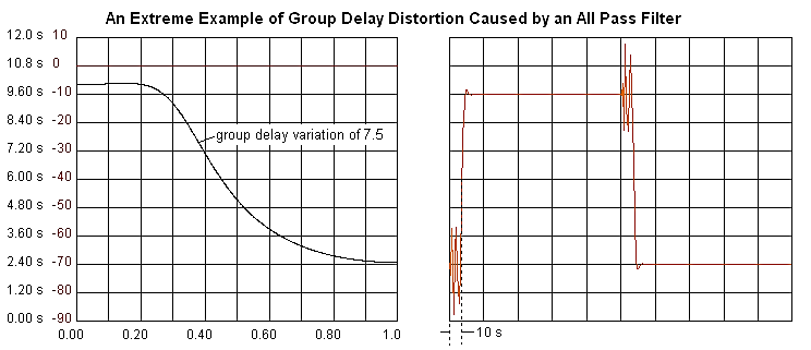
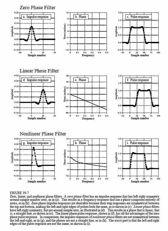
주파수에 따른 위상 특성: 주파수에 따른 group delay
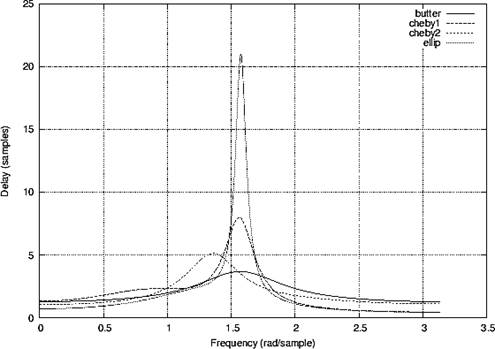
- Group delay
- Derivative
of the phase with respect to angular frequency
- A
measure of the distortion in the signal
- TEM
전송선/평면파의 군지연 시간 = 신호통과시간: 주파수에 무관
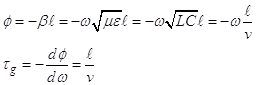
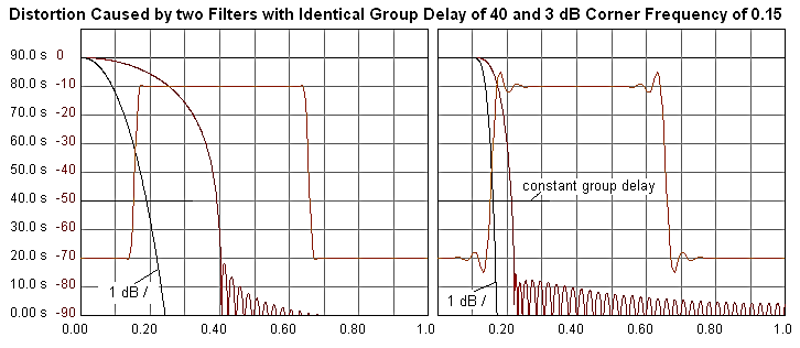
- 필터의 군지연시간: 주파수의 함수 → 신호왜곡 발생
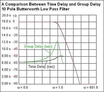
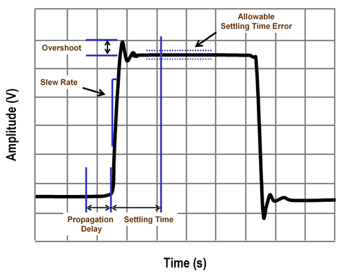
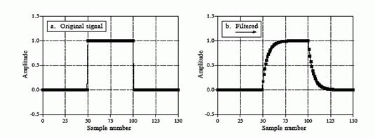
- 저역통과필터에 의한 펄스파형 왜곡
ㅇ 필터에 의한 신호왜곡
- 펄스신호 규격
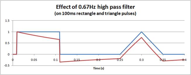
- 저역통과 필터
- 고역통과 필터
2. LC 필터
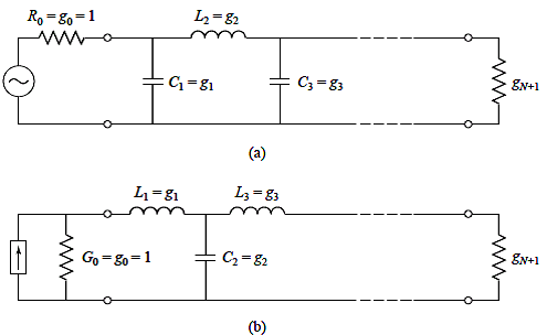
1) 원형(prototype)
저역통과필터
ㅇ 필터 회로 topology
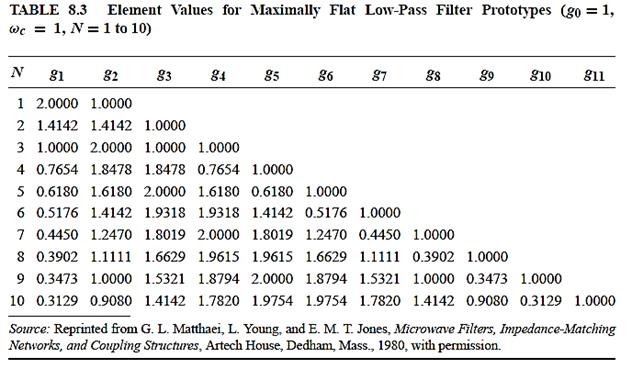
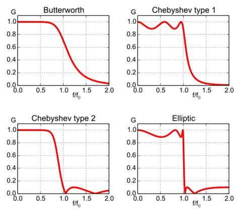
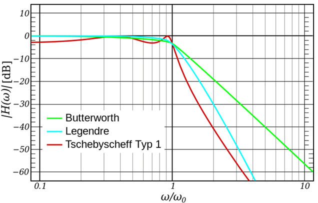
A. Butterworth Filter (= Maximally Flat Filter)
ㅇ 통과대역 진폭특성이 가장 평탄하다.
ㅇ 통과대역에서 임피던스 정합 완벽 (반사계수 0)
![]()
g0: source resistance or conductance
gN+1: load resistance (if gN is a shunt capacitor) or load conductance (if gN is a series inductor)
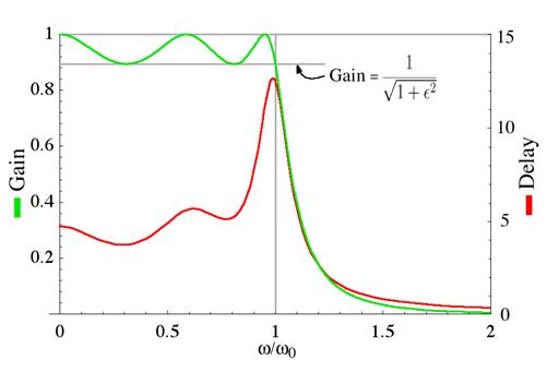
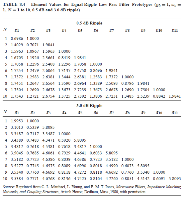
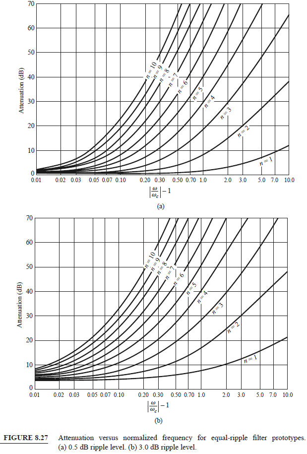
B. Equi-Ripple Filter (= Chebyshev Filter)
ㅇ 통과대역 진폭특성이 평균값을 기준으로 동일한 크기로 최대값, 최소값을 가지며 변화
ㅇ 차단주파수 이상에서 감쇠율이 가장 크다.
ㅇ 통과대역 리플 크기에 따른 통과대역 반사계수
리플(dB) 반사계수(dB)
0.1 -33
0.25 -25
0.5 -20
1.0 -14
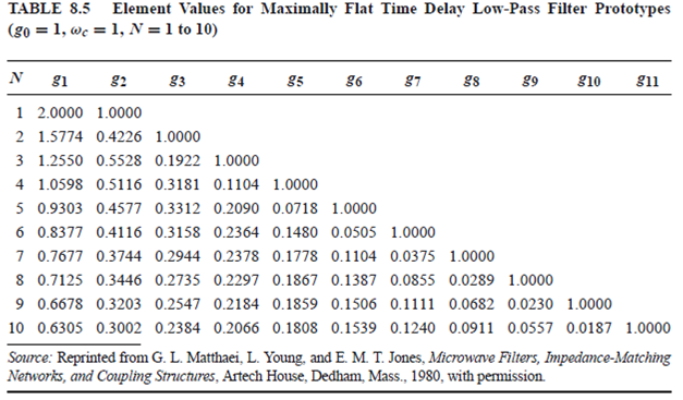
C. Linear-Phase Filter ( = Bessel Filter)
ㅇ 통과대역 군지연이 가장 평탄: maximally flat group/phase delay, maximally
linear phase response
ㅇ 차단대역 감쇠속도 가장 느림
ㅇ 용도: audio crossover 시스템
ㅇ 선형위상 FIR 필터
D.
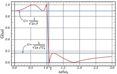
Elliptic Filter (= Cauer Filter)
- 통과대역과 차단대역에서 동일한 ripple
- The
amount of ripple in each band is independently adjustable, and no other filter
of equal order can have a faster transition in gain between the passband and
the stopband, for the given values of ripple (whether the ripple is
equalized or not). Alternatively, one may give up the ability to adjust
independently the passband and stopband ripple, and instead design a filter
which is maximally insensitive to component variations.
- As the
ripple in the stopband approaches zero, the filter becomes a type I Chebyshev
filter. As the ripple in the passband approaches zero, the filter becomes a
type II Chebyshev filter and finally, as both ripple values approach
zero, the filter becomes a Butterworth filter.
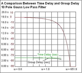
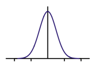
E. Gaussian
Filter
- 임펄스특성이 가우스 함수: 입력신호가 임필스일 경우 출력신호가 가우스 함수
- 특징:
계단함수 입력시: overshoot 미발생, 상승/하강시간 최소, minimum possible group delay
이상적인 시간영역 필터 (참고: 이상적인 주파수영역 필터는 sinc 필터)
F.
Optimum "L" Filter ( = Legendre-Papoulis Filter)
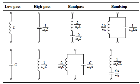
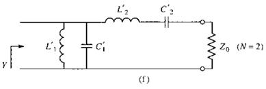
2. 필터변환(Filter Transformation)
ㅇ Impedanc and frequency scaling
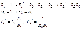
ㅇ Filter type transformation
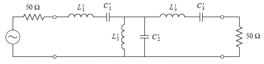
![]()
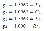
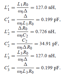
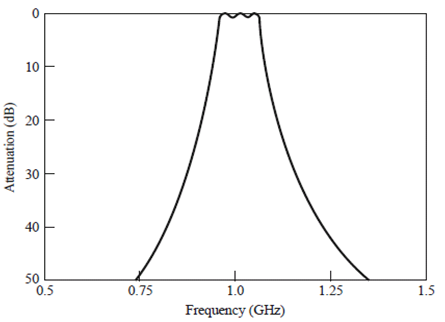
ㅇ Design example:
0.5-dB
equi-ripple
N = 3
fc = 1GHz
Bandwidth
= 10%
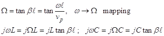
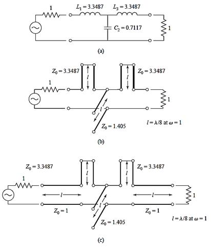
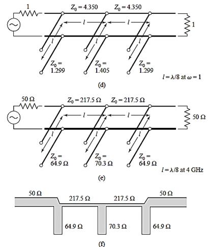
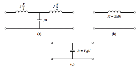
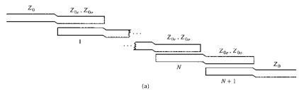
3. 전송선 필터
Richards'
transformation: for implementing L and C with short-circuit and open-circuit
transmission lines respectively
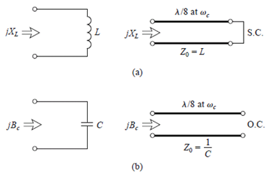
![]()
Inductor:
short-circuit transmission line of length λ/8,
L → Z0
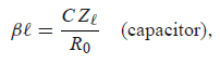
Capacitor:
open-circuit transmission line of length λ/8,
C → 1 / Z0
A. Stub-loaded low-pass filter
B. Design example: 3-dB equi-ripple, LPF, 3GHz,
50Ω
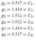
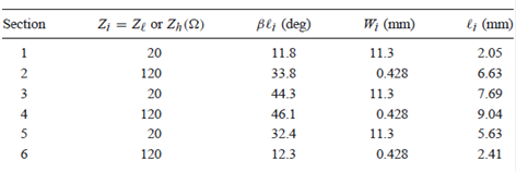
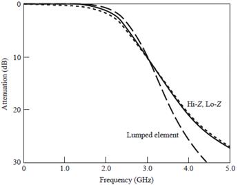
C. Stepped impedance LPF
![]()
Design
example: maximally flat, fc
2.5GHz, 20dB insertion loss at 4GHz, 50Ω
microstrip
impedance range: 20-120Ω
er
=4.2, tand = 0.01, 0.5-mil substrate
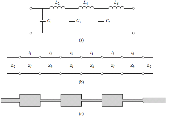
N = 6 from attenuation requirement
D. Coupled-line BPF
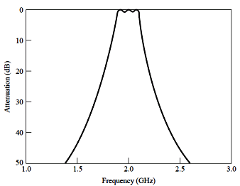
Coupled-resonator
filters
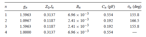
Design
example:
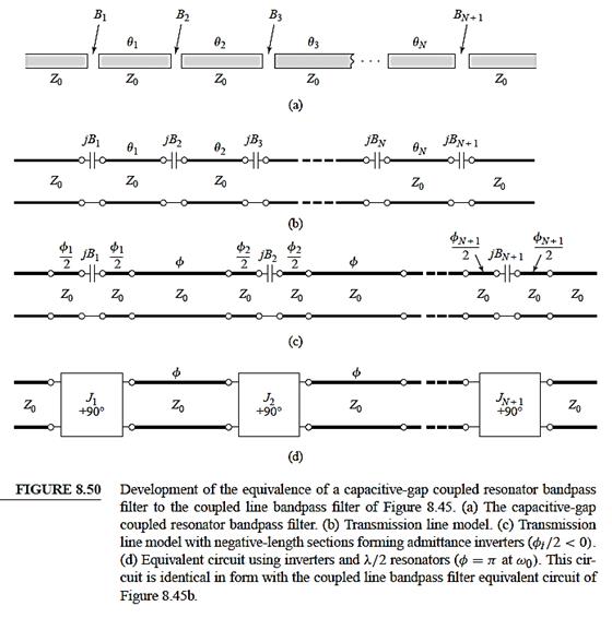
Capacitively-coupled
series resonator BPF
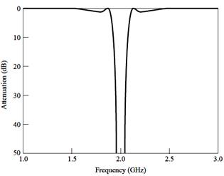
Degisn example: 2.0GHz, 0.5dB equi-ripple, 10%, 20dB at 2.2GHz
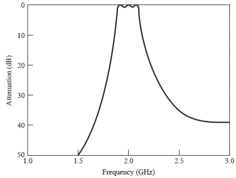
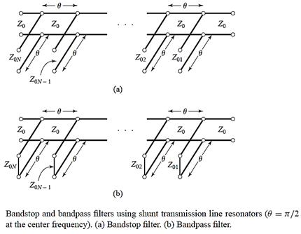
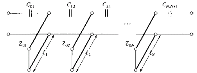
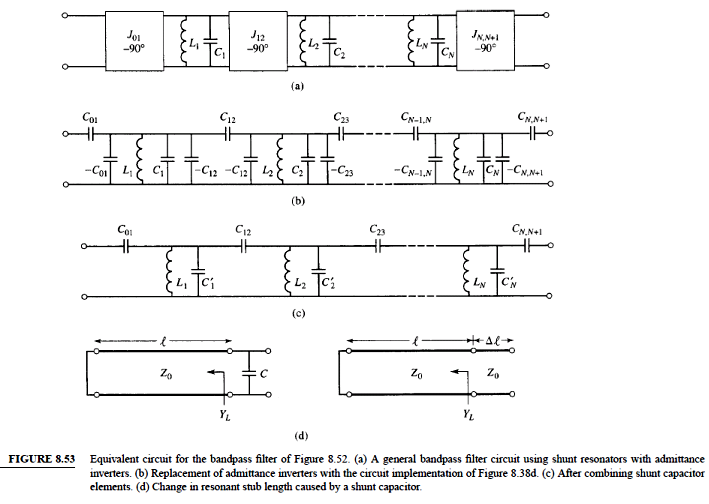
BPF using capacitively-coupled shunt resonators
II. 실습
RF Tools의 LC Filters Design Tool에 접속: https://rf-tools.com/lc-filter/
아래 필터를 설계하고
회로도
Insertion loss
/ return loss 그래프
Phase and grou
delay 그래프
도시
1. LPF 설계
차단주파수: 100MHz
차수: 5
전원 저항: 50Ω
부하 저항: 50Ω
형식: Chebyshev, shunt first, 0.25-dB ripple
2. BPF 설계
통과대역: 190-200MHz
차수: 5
전원 저항: 50Ω
부하 저항: 50Ω
형식: Chebshev, shnut first, 0.25-dB ripple
III. 과제
아래 필터를 수작업으로 설계한 후 RF Tools LC Filters Design Tool의 결과와 비교하고 insertion loss / return loss 그래프, phase delay / group delay 그래프를 도시
1. LPF 설계
차단주파수: 100MHz
차수: 5
전원 저항: 50Ω
부하 저항: 50Ω
형식: Butterworth, shunt first
2. BPF 설계
통과대역: 190-200MHz
차수: 5
전원 저항: 50Ω
부하 저항: 50Ω
형식: Butterworth, shnut first