Measurements in Radio Engineering
Lab01-Mutual
Inductance Measurement
1. Motivation
-
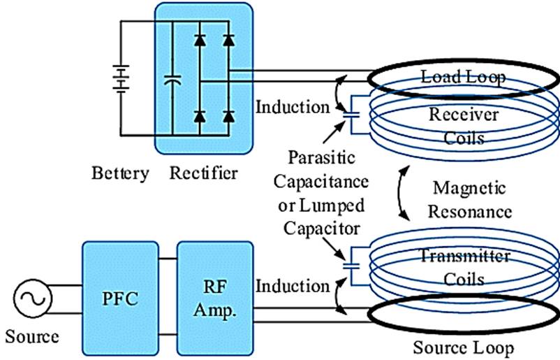
Wireless charging

-
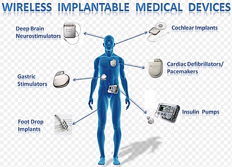
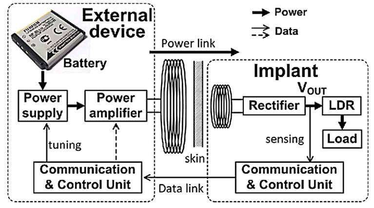
Wireless power transfer for implanted devices
-
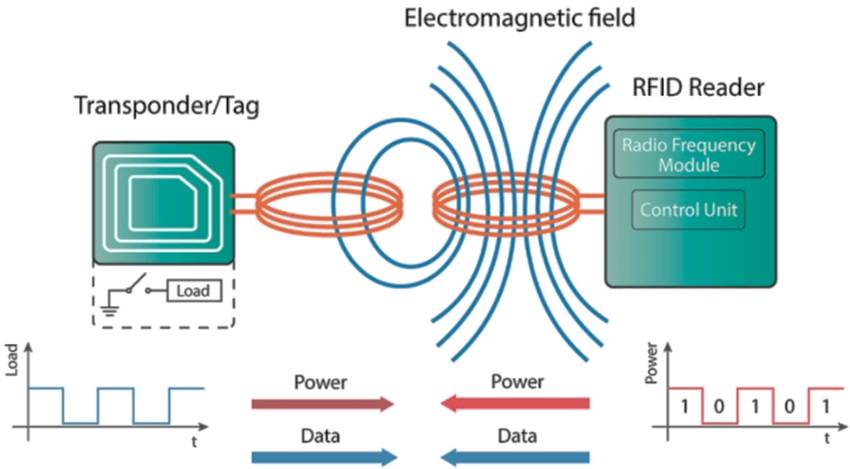
NFC/RFID
2. Theory
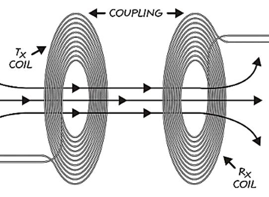
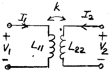
Two coils
placed close to each other can be represented by the following circuit.
2.1 Inductance Only Measurements
From the
basic circuit theory, we can write
![]() (1)
(1)
![]() (2)
(2)
With ![]() , we obtain
, we obtain
![]()
Measure
the primary coil inductance using an LCR meter with the secondary coil
open-circuited to obtain L11.
 (3)
(3)
Similarly
measure the secondary coil inductance with the primary coil open-circuited to
obtain L22.
 (4)
(4)
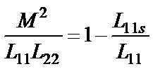
With the
secondary coil shored, we have
![]() (5)
(5)
Use (5)
in (1) to obtain
 (6)
(6)
From (6)
 (7)
(7)
 (8)
(8)
Quality
factor:
 (9)
(9)
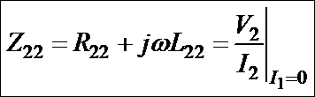
2.2 Inductance and Resistance Measurements
![]() (11)
(11)
![]() (12)
(12)
 (13)
(13)
 (14)
(14)
With the
secondary circuit shorted:
![]()

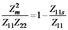
 (15)
(15)
 (16)
(16)
3. Measurements
3.1 Two identical coils with zero coil gap
f = 100kHz
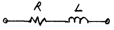
Use a
series equivalent circuit for the inductance measurement.
Use L, Q
measurement
1) Measure L11
and Q11.
2) Measure L22
and Q22.
3) Measure L11s
and Q11s.
4) Find k.
5) Find M.
3.2 Repeat 1 with 3-mm coil gap.
4. Sample Results
- Use 'COUPLED COIL ANALYSIS'
- Coils used: 2 units of Abracon LLC
AWCCA-50N50H35-C01-B
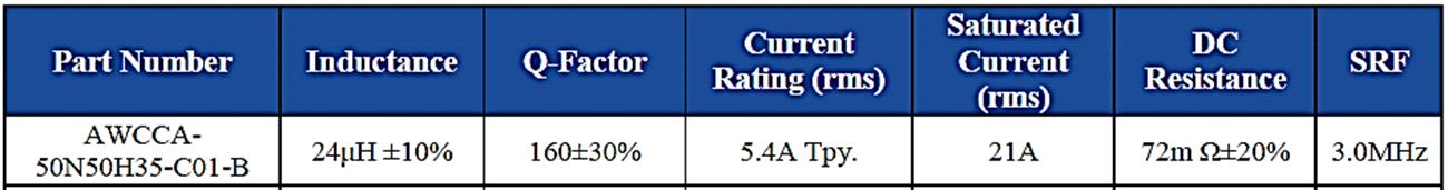
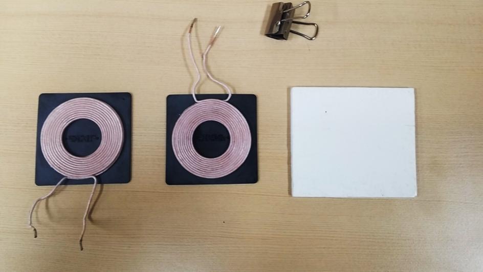
Figure: Materials for mutual inductance
measurements. Two 100-kHz inductive charging coils (Abracon LLC
AWCCA-50N50H35-C01-B), a 3-mm thick spacer, a paper clamp for short-circuiting
the secondary coil
- Coil gap = 0mm
* Measurements: 100kHz, Ls-Q, Keysight E4980A LCR
meter (20Hz-2MHz)
L11, Q11: 46.6uH, 188
L22, Q22: 46.6uH, 188
L11s, Q11s: 7.53uH, 27
* Calculation:
R11, R22 (ohms): 0.156, 0.156
k = (0.916, 0.0028)
Rm, Lm, Qm: 0.061, 42.7uH, 442
- Coil gap = 3mm
L11, Q11: 33.2uH, 184
L22, Q22: 33.2uH, 184
L11s, Q11s: 15.8uH, 72
* Calculation
R11, R22 (ohms): 0.113, 0.113
k = (0.724, 0.0028)
Rm, Lm, Qm: 0.024, 24.0uH, 626